Soil-structure interaction is a crucial aspect for both geotechnical and structural fields. There is always an interaction between a structure and its foundation … and its proper investigation is an important design aspect which should not be neglected.
PLAXIS offers extensive modeling features to model structures and the interaction between the structures and the soil. You can successfully perform projects of any kind, such as:
- Excavations
- Both shallow and deep foundations
- Embankments
- Tunnels
- Mines
- Dredging
In this context, it is very important to properly evaluate the structural forces that develop during project construction. Here is an overview of available structural elements as well as different techniques to visualize structural forces in PLAXIS.
Structural elements library
Extensive choice of structural elements
PLAXIS provides a large choice of structural elements:
- Anchors
- Beams and embedded beams
- Plates
- Geogrids
- Interfaces
These structural elements can be used to represent all commonly used structures in geotechnical engineering (See Figure 1).
Anchors are the simplest type of structural elements. Although available in two distinct forms (node-to-node and fixed end anchors), the underlying element technology is identical and simply corresponds to a unidirectional spring that can only support normal action. It is mostly used to model struts and free length of soil/rock anchors.
Beams and embedded beams are line elements which are formulated based on the classical Timoshenko beam theory. They can resist normal actions and bending moments along with associated shear forces. The simple beam elements are only offered in PLAXIS 3D and are supposed to be rigidly connected to the surrounding soil elements with which they are sharing the same nodes along their supporting lines. They are used to model structural beams for which soil-structure interaction is non-existent or irrelevant. The embedded beams element is formulated based on the same beam theory, but with additional nodal non-linear coupling springs placed between the beam nodes and the surrounding soil nodes along their supporting lines. The coupling springs have their specific stiffness and strength properties which allow for the consideration of soil-structure interaction. Embedded beams elements are available in both PLAXIS 2D and 3D and are used to model piles and grouted bodies of soil/rock reinforcements.

Plates in PLAXIS are also offered in both 2D and 3D modeling environments and are formulated based on the Mindlin-Reissner theory. Equilibrium equations of the plate introduce:
- In-plane normal forces (2 components)
- Bending and twisting moments (2 + 1 components respectively)
- Transverse shear forces (2 components)
Plates can be used for a large variety of structures, including:
- Retaining walls
- Raft foundations
- Tunnel linings
- Building floors and walls
- Cofferdams
Geogrids could be considered as “degenerated” plate elements only capable of supporting tensile loads (no compressive normal forces, no bending moments, no transverse shear forces). Geogrids are used as reinforcing elements which are embedded within the soil mass and improve stabilization through a load transfer mechanism between the soil and the reinforcement. They are ideally used in PLAXIS in combination with large-displacement analysis for the proper consideration of the so-called membrane effect.
By introducing an interface along a line (or a surface in 3D), node pairs are created at the interface between the soil and the structure (one node belonging to the structure and the other one belonging to the soil). The interaction between these two nodes are then controlled by the behavior of a set of elastic-perfectly plastic springs. One elastic-perfectly plastic spring is positioned along the normal direction to model the gap displacement, and one (or two in 3D) elastic-perfectly plastic spring(s) sits along the lateral directions(s) to model slip displacement. The interface elements are meant to behave according to the relatively simple rule: “stick or slide.” When the interface’s stresses remain below the user-defined strength (tensile or shear depending on whether one is considering normal or lateral directions), extremely small elastic reversible relative displacement will be generated through the consideration of arbitrarily large interface elastic stiffnesses. As soon as the specified strength is reached (defined either as a Mohr-Coulomb shear failure or a tension cut-off criteria as shown in Figure 2), irreversible relative displacement will be generated without further stress development.

Output results
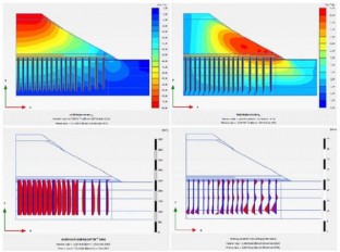
Structural elements use normal forces, shear forces, and moments as primary variables to enforce equilibrium. As such, these structural elements are directly computed by the calculation kernel and reported into the post-processing environment (PLAXIS Output) as shown in Figure 3. This is convenient from a structural engineering point of view for the design and dimensioning of cross sections and elements thicknesses, as well as the assessment of steel reinforcement quantities.

Modeling structures as solid elements
Motivation
The accuracy of the structural element response is primarily related to its slenderness ratio. The idealization of its kinematics in a given direction(s) requires some structural dimensions (cross section for beam/anchors and thickness for plates/geogrids) to be small compared to other dimensions, enabling the simplification of their geometrical representation (to a line for beam/anchors and to a surface for plates/geogrids). As a rule of thumb, people usually consider an order of magnitude (roughly a factor of 10) as a good slenderness criterion. If such criterion is not met the use of structural elements is questionable. As a practical example, one can think of a thick raft foundation which would be 10 m long and 2 m thick, for instance.
Geotechnical engineers might also face situations where structure sections are non-uniform (tapered members, for example) or cases that have a detailed presentation of the soil-structure interface geometry. An illustration of the latter would be a consideration of the physical thickness of the structural members to analyze soil pressure development. For instance, you could examine along the extrados of a tunnel cross section with relatively low curvature radius, or simply the lowest surface of the raft (instead of the middle surface, should the raft have been modeled through plate elements). In this context, structural members can also be equally presented as volume elements, as shown in Figure 4.

The representation of the structural members by volume elements will always lead to a more accurate description of the physical problem, but usually at the cost of a more sophisticated model. A larger number of elements can be considered, compared to a situation where structural elements would have been used in the first place. This could result in significantly longer modeling time in terms of model construction plus analysis run and post-processing time.
Structural forces evaluation
Another possible drawback of modeling structural members by mean of volume elements is the absence of structural forces being directly output. Like any other volume elements (usually used for soil with appropriate constitutive model and associated stiffness and strength parameters), only stresses are available for post-processing. This might be inconvenient for structural engineering design purposes.
Luckily, this can be remediated by two techniques that PLAXIS offers for increased productivity:
- Structural Forces in Volume calculation tool in PLAXIS Output: This functionality consists of integrating stresses within a set of pre-selected volume clusters that refer to a so-called “centerline” representing the neutral axis of the section. The volume sections within the pre-selected clusters and where the stress integration takes place are set perpendicular to the centerline. The centerline is also used to compute the lever arm for each stress contribution in the calculation of the corresponding bending moments.
- Fictitious soft structural elements (often referred to as “Dummy” elements) can be set along the neutral axis of the structural members (see Figure 5). The purpose of these dummy elements is to monitor the evolution of the axial deformation and change of curvature without introducing significant stiffness contribution to the volume structural members.
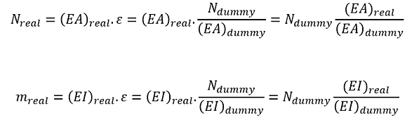
 structural embedded beam element or (b) solid element with dummy beam")
Sources: Model Structures and Visualize Structural Forces, PLAXIS Productivity Strategies Blog
Want to read more like this story?
How to Model Piles in PLAXIS
Jun, 17, 2021 | NewsThe problem of analyzing and designing deep foundations is relevant to many civil engineering struc...

The PLAXIS Tunnel Engineer’s Toolbox: Everything You Will Need In One Place
Jun, 28, 2024 | NewsPLAXIS offers a wide range of tools to the Tunnel Engineer, which can be combined to generate almos...
PLAXIS for Deep Underground Excavation in Rock Mass
Mar, 01, 2022 | NewsRock at depth is subjected to stresses resulting from the weight of the overlying strata and from l...

GEO5 FEM
Aug, 16, 2019 | SoftwareFinite Element / Finite Difference
Oct, 13, 2025 | EducationOverview The Finite Element Method (FEM) has established itself as a powerful numerical technique i...

PLAXIS 2023.2 New release is out!
Sep, 07, 2023 | NewsThis latest release solidifies Seequent's Connected Geotechnical Workflow, reducing the need for du...

3D Modeling of Soil-Foundation-Structure Interaction: Case History at Fly Ash Silo, Maasvlakte Rotterdam
Sep, 14, 2020 | EducationNote: This Case History was first presented in Plaxis Bulletin, Autumn issue 2013, by L.F.J. Bekke...

PLAXIS – From Concept to Construction
Mar, 03, 2022 | NewsImporting geometric and stratigraphic data to PLAXIS 3D Any infrastructure project begins with a t...
Optimizing Soil Improvement with PLAXIS: Techniques and Benefits
Nov, 12, 2024 | NewsSoil improvement refers to the process of modifying the physical properties of soil to improve its...
Form
Looking for more information? Fill in the form and we will contact Bentley for you. Alternatively, you can visit Bentley's website and speak with a Bentley Geotechnical Expert.
On This Day
August 2nd 1982
READ MORE
Related Video

Trending

Seequent announced extended gINT support until Dec 31, 2028
New Release: GeoStudio 2025.2

Artificial Ground Freezing: Applications, Techniques, and Key Considerations
Brownfield success: Engineering excellence starts below ground
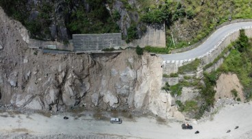
Nepal’s Himalayan settlements face escalating flood and landslide threats