An introduction of Micropiles on expansive and karst ground conditions through the design lens of bearing capacity
Contents [show]
- Abstract
- Historical Background
- Mircropiles as Deep Foundation elements
- Bearing Capacity of Micropiles
- Theoretical calculations from Vesic 1963
- Bearing capacity in cohesionless and cohesive soils
- Cohesionless soil: Sands
- Cohesive soil: Clays
- Expansive and Karst ground conditions
- Expansive Soils
- Karst Topography
- Conclusion
- Appendix
- Work Cited
Abstract
The history of micropiles stems over seven decades ago from Europe though widespread acceptance and standardization of the technology is more recent and has not matured for as long as its first documented use in 1950s Italy. Micropiles were largely introduced as a solution to provide additional support to unstable structures. Present use cases still reside primarily within the context of deep foundation design engineering. With more documented usage of micropiles in broader applications, the body of knowledge in this niche of foundation design accumulates. This paper aims to provide students with interest in geotechnical and/or foundation engineering basic understanding to the use of micropiles in deep foundation applications. It introduces the reader to the basic use of micropiles, provides theoretical background knowledge on bearing capacity calculations, and explains the functionality and benefit of micropiles within the context of expansive and karstic ground conditions. Though beyond the scope of the paper, micropiles are also a viable option for other geotechnical engineering design challenges, namely with regards to slope stabilization, earth retention, and ground strengthening. In addition to bearing capacity considerations, the practical micropile design process also accounts for settlement requirements, but the theoretical calculations for this design consideration is not covered in this paper.
Historical Background
Micropile technology emerged from a 1950s design challenge in Europe. Set in post WWII Italy, historical structures required additional support due to age related deterioration intensified by disturbance from war. Civil engineer, Fernando Lizzi, developed the palo radice, a small diameter drilled and grouted pile, which we now refer to as micropiles (Mason and Bruce 2001). Micropile technology at the time was heavily used for underpinning building foundations to provide additional support to weakened historical unreinforced masonry structures due to differential stress. Lizzi’s core concept of micropiles, also referred to at the time as the internal reinforcement method (IRM), which describes gravity grout casted reinforcement in a drilled hole, remains virtually the same. With the advent of better technology used for micropile installation and an increasing pool of knowledge for their standard use, micropile applications are becoming a more viable design solution option in our civil infrastructure. Lizzi utilized IRMs for underpinning foundation and overtime, with more documented studies, micropile use broadened to span other in-situ reinforcement (e.g., slope stabilization and earth retention, ground strengthening, settlement reduction) and structural support (e.g. seismic retrofitting, earth retaining structure foundations, upgrading foundation capacity) applications (Sabatini et. al 2005).
Mircropiles as Deep Foundation elements
Micropiles are deep foundation elements used for structural reinforcement between above grade structure and below grade soil structure. Micropiles (or minipiles) are small diameter, cast in place grouted columns used as load transfer elements from the supported structure above grade to the sub-soil skeleton. The Federal Highway Administration (FHWA) categorizes the use of micropiles between structural support, encompassing all usage of micropiles in the extent of foundation reinforcement and seismic retrofitting, and geotechnical support, encompassing the smaller portion of use for in-situ ground improvement relating to slope stability and differential settlement (Sabatini et. al 2005). Publications by the FHWA in the late 1990s detailing the practical use of micropiles largely contributed to the legitimization of the use of micropiles for addressing design challenges as it relates to structural support or in-situ ground improvement techniques.
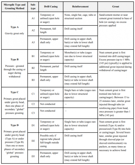
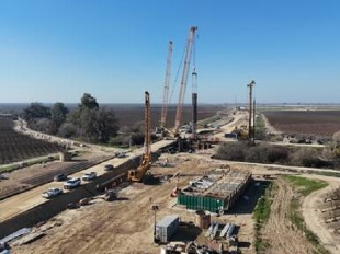
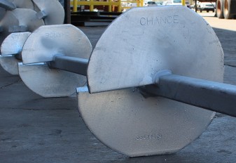
Whether micropiles are utilized for structural or slope stabilization purposes, there are several key considerations that would favor the use of micropiles. Some of these considerations are based on site conditions (e.g., pile driving can induce liquefaction), machinery access (e.g., remote environments, small spaces, and existing obstructions), and cost (e.g., determining if the cost per kilonewton of force provided by the micropile installation is financially acceptable). Though micropile installation can vary due to drilling techniques and the considerations previously stated, the installation process can be generalized to three steps: The first step is drilling a hole wherein the support element will be casted in. Depending on the site conditions, the most cost-efficient and least disturbing drilling technique can be employed along with drilling liquid (slurry) or outer drill casing to prevent internal collapse while drilling to the desired depth of a competent soil stratum. A steel rod is inserted securely along the centerline of the bored hole (step 2) and the opening is encased with grout from the top of the competent layer to the desired length of the micropile element (step 3). Variations of the reinforcement material and grout used are integrated in the design process ensuring the load is sufficiently supported either by the skin friction between the grout-soil interface, the end bearing capacity, or a combination of both. From previous studies and experimentation, we know that as deep foundation elements, micropiles will largely derive its bearing load from friction between the soil-grout interface. An additional layer of complexity in creating a micropile element is introduced in the installation process of the grout itself. Figure 4 visually highlights four types of micropiles with differing grout installations ranging from simple grouting with only gravity head (Type A) to a two-step process using pressurized grouting method (Type D), which reveals a modified profile of the end product of the micropile (Perkins 2015, Shong and Fong 2003). See appendix for Details of Micropile Classification Based on Type of Grouting (after Pearlman and Wolosick, 1992). Different type grouting is a function of cost, availability of materials, and the intended design capacity of the piles.

Bearing Capacity of Micropiles
The following section introduces past literature detailing different methodologies for calculating the ultimate bearing load of a single pile. It is worth noting that the information herein is not inclusive of all other methods for calculating load bearing capacity of a vertical pile (e.g., using SPT/CPT and field load testing). Further design requirements relating to settlement considerations is also crucial for practical implementation of micropiles in foundations, but is not explicitly covered in this paper.
The bearing capacity of a material is a measure of the amount of load it can sustain and transfer to subsequent elements, in this case the load transfer to the surrounding soil skeleton. The ultimate bearing capacity is a fundamental concept in solid mechanics indicating the maximum contact pressure a support element can sustain from other load bearing elements before failure. In soil mechanics, bearing capacity of soil is the load it can sustain without shear failure. It is a function of the soil shear strength and the shape for the footing. The ultimate bearing capacity largely dictates the allowable bearing capacity an element will be designed to sustain to ensure an acceptable design factor of safety for the overall structure.
Theoretical calculations from Vesic 1963
The general equation to determine the ultimate bearing capacity load Q this foundation can support is defined as:
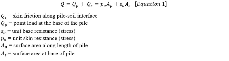
Total average failure load of a single pile:

Point bearing load at the end base of a single pile:

Bearing capacity in cohesionless and cohesive soils
Load dissipation through piles is largely through the soil-grout interface as stipulated by the theoretical understanding of the pile bearing capacity and validated through prior independent experimentations. Despite its smaller diameter, micropiles do have an end bearing capacity, but it’s often negligible. As a stabilization technique, micropiles can be implemented to locally improve carrying capacity to support the loads from the structure above. The specific cases we will generalize are the use of micropiles on cohesionless and cohesive soil.
Cohesionless soil: Sands
Cohesive soil: Clays

Expansive and Karst ground conditions
Design challenges rooted from site characterization of unfavorable site conditions can be a good opportunity wherein micropiles can be implemented. The following section features two scenarios where micropiles were used specifically addressing site conditions with expansive soils and karst topography.
Expansive Soils
Expansive soils pose a design challenge for geotechnical engineers because, by nature, this element is dynamic and so micropile design considerations must account for a tolerable range of fluctuations in soil volume. Expansive soils can be found in large swaths of southwestern United States, India, and Australia, and some parts of Africa and the Middle East (Bowles 1996). These regions experience cyclical dry and wet seasons which drive the volumetric expansion and contraction of soil structure as water content in the soil fluctuates over different seasons. Designing a structure on top of these soil structures, regardless of whether construction was done over the dry or wet spell periods, will subject the structure to contractive or tensile forces, inducing a pressure differential on the base of the structure, along the soil-structure interface, creating cracks permeating from the soil-structure interface.
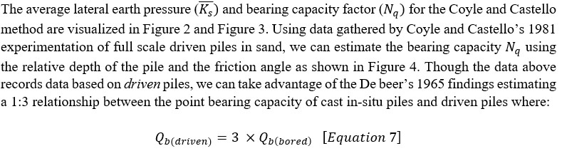
Building an adequate foundation in such cases where the high plasticity soil conditions pose serious risks of differential settlement, micropiles can be integrated into a concrete slab design to secure the structure into a depth of stable soil strata (Kalantari 2012). Given poor soil structure, the bored piles are embedded through the dynamic layer onto the stable zone layer. This stable zone is not necessarily at bedrock, it is simply a soil structure that does not undergo cyclic volume changes to offer counteractive tensile forces along the soil-grout interface against the uplift pressures from the swelling soil. Figure 6 illustrates a schematic of this concept with a pile/pier experiencing uplift at the unstable zone and resistive pressures at the stable zone. The figure also shows that the grade beam is elevated on piles, trapping air pockets between the slab and the vertical elements, which would facilitate “air circulation and evaporation below the structure [and can lead to] minimal disturbance to the water content of the swell-susceptible strata” (Patel 2019). These air pockets also provide free space for the dynamic soil to expand, which will prevent excess buildup of pressure; cavities in waffle cone slab designs serve this similar purpose. In this case, because the dead load from the structure is not necessarily transferred to the end of the pile, the load path design of this slab-pile hybrid relies more on the skin friction along the surface of the pile to transfer the load to the ground than the end bearing capacity. Though Kalantari did not specifically take note of this benefit on the paper, we assume that in this generic design scenario, the associated cost from removing and replacing the unstable layer outweighs the supplemental material and labor cost for integrating micropiles to the foundation design.
Karst Topography
Unlike site conditions for expansive soils where volume change and associated uplift pressures are the prime design drivers, design considerations for karstic conditions are driven by absence of soil volume. Karst topography is characterized by heterogeneous distribution of voids, caves, and sinkholes from dissolution of carbonate rocks, such as limestone and dolomite. Naturally eroded by the scour of water flow, karst topographies are not directly suitable for construction activities due to fractures and joints that compromise an otherwise competent hard rock stratum (Traylor et al 2002). A thorough site investigation is critical when in karstic environments where soil conditions likely have a high degree of variability from one exploratory borehole to another.
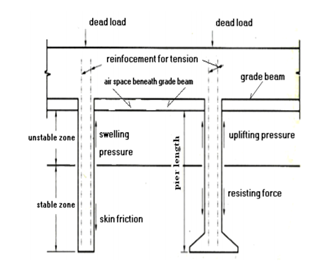
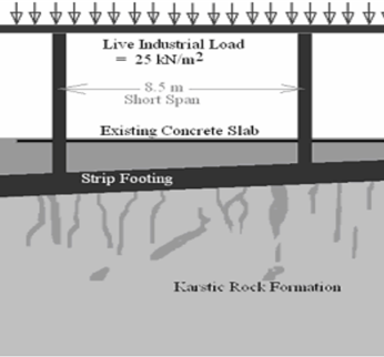
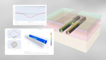
The Sanita factory located in Zouk-Mosbeh, Lebanon was subject to the same constraints having been designed on a one-meter thick high plasticity silt cover on top of a karstic rock formation (Ballouz 2012). Although access to a hard rock stratum merits a shallow foundation design to transfer structural loads to the bearing soil, unstable and unpredictable conditions from the weakened geography needs critical design consideration. The original designs included seven strip footing foundations to be excavated at bedrock (Figure 7), but it proved to be time and cost inefficient. Ultimately, a combined micropile and footing foundation (CMFF) was utilized for this project where the end bearing capacity of the footing and the frictional capacity of the micropiles both contribute to the ultimate bearing capacity (Figure 8). Across all the spread footings supporting the structural elements of the Sanita factory, a total of 386 Type B piles, grouped beneath each footing, were used. Pressure grout injection pushed the cohesive material along the full length of the pile as well as the preexisting fissures in the rock to help ensure a strong bonding zone between the pile and the surrounding soil and rock. On-site axial compression static load tests were conducted to determine the load deflection characteristics of the pile-soil foundation and ultimately learn a safe bearing capacity that can be applied to the piles. Figure 9 describes the load transfer relationship between the applied load and the depth of the pile, which again reaffirms that end bearing capacity of piles contribute a minor difference to the ultimate bearing capacity. The use of micropiles in this project proved to be cost and time efficient: reducing the labor and material costs for more excavations and optimizing the project schedule to locally excavate at multiple footings at the same time.
Conclusion
Appendix
Work Cited
 Parson Jericho Galicia
Industry News


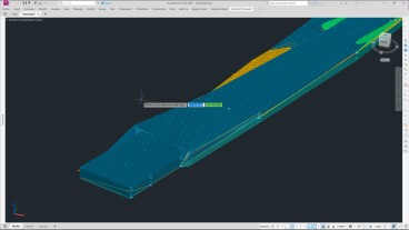
Enable true ground-informed design in Civil 3D


Events

19th European Conference on Soil Mechanics and Geotechnical Engineering, Istanbul, Türkiye

The 10th International Congress on Environmental Geotechnics

11th European Conference on Numerical Methods in Geotechnical Engineering

1st International Conference on Sustainability in Geotechnical Engineering (ICSGE 2027)

The 4th International Conference on Press-in Engineering 2027 (ICPE2027)

International Symposium on Cone Penetration Testing (CPT'27)

Rocscience International Conference 2027: Geotechnics, Structures & Hydro in the Age of AI
IS-GI Lyon 2027: International Symposium on Ground Improvement