Contents [show]
Introduction
Helical piles are a form of prefabricated deep foundation. As hinted in its name, helical piles differ from other deep foundations and are most notable for having spiraling blades along their shafts, as opposed to having a relatively uniform shape like driven piles and micropiles.
Some other names for helical piles include helical piers, helical anchors, screw piles, and screw foundations. While there may be some minor differences in particular naming conventions, these names are often used interchangeably. At the very least, the principle between all of these remain the same.
Basic Description

Fig. 1: Basic helical pile (Perko 2009)
The first piece of the helical pile is called the lead; this is the piece that is first rotated into the ground. The lead has multiple helical blades, also referred to as helical bearing plates, that can vary in size, shape, and number. After the lead follows any number of extensions, depending on the required torque or depth. These are simply shafts that are bolted and pinned to the lead and to each other at their ends. The top of the pile is the incorporated into the foundation system via a bracket or other connection method.
The shaft can come in either a circular or a square cross section shape and is typically hollow.
Compressive Performance

Fig 2: Compression failure modes (Perko 2009)
The soil supporting the helical piles can fail in bearing in two fashions: either the soils fail locally at each plate (individual bearing) or the soils between plates fail and move as a group (cylindrical shearing), as seen in Figure 2.
For individual bearing, the ultimate bearing capacity, Pu, is the sum of the bearing capacity on the plates plus the adhesion resistance on the shaft above the uppermost bearing plate. The equation is given by

where An is the area of the nth plate, qult is the ultimate bearing pressure of the soil, α is the adhesion between the soil and the shaft, H is the distance from the uppermost bearing plate to the top of the shaft, and d is the diameter of the shaft. qult can be calculated from a variety of methods, like the Terzaghi, Meyerhof, or Hansen and Vesic equations (Perko 2009).
For cylindrical shearing, the ultimate bearing capacity is calculated from the sum of the bearing force applied to the bottom bearing plate, the shear force on the mobilized soil between the bearing plates, and the adhesion resistance on the shaft above the uppermost bearing plate. Following this methodology, the equation is given by

where A1 is the area of the lowermost bearing plate, T is the soil shear strength, L is length of the mobilized soil between the uppermost and lowermost bearing plates, and D is the diameter of the bearing plates. The remaining terms remain the same as that described in the individual bearing equation (Perko 2009).
The deflection, δ, of helical piles in compression is given by the best-fit power function

where λδ is a fitting constant of 4.33 inches, and N70 is SPT blow count with an energy ratio of 70. x is a fitting constant, equal to 0.37 for piles with shaft diameters between 2.875 inches to 3.5 inches. For piles with shaft diameters between 4.5 inches to 10.8 inches, x is equal to 0.56, meaning that piles with larger shaft diameters tend to deflect less (Perko 2009).
Similar to most other deep foundation systems, helical piles typically do not need to be considered in buckling failure, unless placed in fluid conditions. The International Building Code specifies that non-fluid soil provides enough lateral bracing to prevent buckling modes of failure. However, in the case that helical piles are designed in fluid soils, or soils with extremely low stiffness and strength, where lateral bracing is insufficient, LRFD or ASD methods should be used to determine the critical buckling loads (Perko 2009).
It is common to use the installation torque as a measurement of axial capacity. The relationship is typically regarded as:
Pu = KtT
where Pu is axial capacity, Kt is the capacity-torque ratio, and T is the installation torque. Kt is typically higher for piles installed in sands than piles installed in clays (Livneh and El Naggar 2008). There are varying models of differing complexity that calculate Kt from various pile parameters, like plate diameter, plate thickness, shaft diameter, etc (Perko 2009).
Tensile Performance
In tension or pullout, the soil supporting a helical pile can fail in individual bearing or cylindrical shearing. In these failure modes, the equations describing the theoretical capacities remain the same as those in compression. A helical pile can also fail if the weight of the soil above the uppermost bearing plate is not large enough.

Fig 3: 45-degree tensile influence cone (Perko 2009)
The weight of the soil resisting tension, W, is given by

where γ’ is the effective unit weight of the soil, D is the diameter of the uppermost bearing plate, z is the distance above the uppermost bearing plate, and θ is the angle of influence, calculated from the vertical (Perko 2009).
Other Design Factors
Typically, a pile with bearing plates has 1.2 to 1.5 times the capacity of a pile with just a shaft (Prasad and Rao 1996).
Helical pile capacity in clays is optimized when the bearing plates are spaced 1.0 to 1.5 plate diameters apart along the shaft (Prasad and Rao 1996). If the plate spacing to plate diameter is greater than 1.5, the failure surface of the soil between plates in uplift is no longer cylindrical, which is correlated with uplift capacity (Prasad and Rao 1993). Further analysis with transparent soils and laser-aided particle image velocimetry has also found that plate spacing ratios less than 1.5 result in a stiffer response and thus less settlement in clays (Stainer and Hird 2014).
The factor of safety used for helical piles is typically around 2.0 as opposed to 3.0 for other foundation systems. This is due to the fact that helical pile capacity can be verified with installation torque using the capacity-torque ratio described previously. Depending on the number of piles inspected and observed, the factor of safety can vary between 1.5 and 2.5 (Perko 2009). In addition, if settlement is an important concern, then a higher factor of safety should also be used (Wilson 1950).

Fig 4: Example helical pier capacity diagram from manufacturer (Perko 2009).
The capacity of a pier is typically provided by the manufacturer. Figure 4 provides an example of a manufacturer-provided chart for determining the proper blade diameter given the needed capacity and SPT blow count (Perko 2009).
Helical piles with circular shafts perform better than piles with square shafts in lateral loading conditions. While short piles with large diameters can be analyzed as rigid bodies in lateral loading conditions, most piles must be analyzed as flexible bodies, where the shaft stiffness is considered. Although the helical bearing plates have been shown to add lateral resistance, this effect should be ignored to be conservative until rigorous analysis has been completed (Perko 2009).
The helical pile must also be embedded deeply enough into the soil such that the weight of the soil above the bearing plates can support uplift forces. In addition, helical piles must be embedded deeply enough to extend past the active failure surface so that their tension and compression capacities are actually engaged (Perko 2009).
The failure criterion often used in practice and noted as appropriate in theory is settlement equal to 5% of the bearing plate diameter (Elsherbiny and El Naggar 2013).
Global Design Configurations

Fig 5: Helical pile with augured concrete cap (Perko 2009).
There are numerous methods and configurations to combat lateral loads with helical piles. As shown in Figure 5, an augured concrete cap is installed by auguring a wider hole along the shaft of the pile and filling it with concrete.

Fig 6: Helical piles installed at batter angle (Perko 2009)
Helical piles can also be installed at batter angles, where the piles provide both lateral and vertical resistance.

Fig 7: Helical piles in a tie-back system (Perko 2009)
Helical piles can also be installed in a tie-back system, where one pile is installed at an angle to provide lateral resistance while another is installed vertically to provide vertical resistance (Perko 2009).
In addition, piles must be placed far enough apart to avoid group action. If placed too closely, the helical pile influence zones can overlap and result in group action. To avoid this, helical piles should be placed at least 4 and 5 diameters apart for piles in compression and tension respectively (Lvneh and El Naggar 2008). In addition, if helical piles are placed too closely, the friction imparted by the soil on the shaft is reduced. However, it seems that the spacing of the piles does not affect the bearing capacity (Wilson 1950).
Construction and Installation

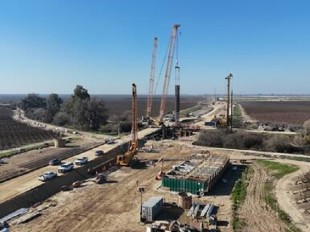
Fig 8: Example installation setup (Perko 2009).
To install the helical pile, a torque motor that can meet the required design torque is all that is really needed. As a result, the installation setup can be incredibly versatile, as the torque motor can be operated by hand or mounted onto machinery.
The piles are rotated into the ground until the desired torque or depth is met (Perko 2009).
Behavior in Different Soils
When comparing the contribution of the shaft and the bearing plates to the axial compressive resistance in clays, the shaft of the helical pile tends to contribute more to load with increasingly stiff clays. The bearing plates carry most of the load, and their contributions increase in proportion as the pile approaches its ultimate axial capacity (Elsherbiny and El Naggar 2013).
When comparing the contribution of the shaft and the bearing plates to the axial compressive resistance in sands, the shaft of the helical pile tends to contribute more to load with increasing density. However, more of the load is carried by the bearing plates in sands than in clays. In addition, the increase in load carried by the shaft with denser sands is much less dramatic than that in stiffer clays. Similarly in clays, the bearing plates in sands carry most of the load, and their contributions increase in proportion as the pile approaches its ultimate axial capacity (Elsherbiny and El Naggar 2013).
In cohesionless soils, helical pile performance is greater in compression than in tension due to reduced uplift resistance (Mohajerani and Bromwich 2016).
When helical piles are embedded in a weak layer of soil followed by a strong layer of soil, the friction of the pile in the weak layer should be ignored, since “the settlement required to develop any support from the soft stratum is much greater than that in the hard stratum” (Wilson 1950). If helical piles are imbedded in a strong layer of soil followed by a weak layer of soil, considerable displacement and settlement should be expected. To account for this, consolidation must be calculated, or the pile can be assumed to lie in the weak layer of soil to be conservative (Wilson 1950).
Depending on the soil conditions, the compressive capacity of a helical pier will be equal to or greater than the tensile capacity (Zhang 1999).
Benefits
A major advantage of using helical piles includes its ease of installation. The equipment required for installation is typically more versatile and maneuverable, making helical piles ideal in confined spaces or when there are existing structures in place (Perko 2009). If necessary, the installation can even be performed manually. Moreover, the installation process is minimally invasive compared to a process involving driven piles, during which the soil is heavily vibrated and can result in nearby structures settling. Also, the installation of helical piles does not disrupt the soil structure (авторов 2017).
Helical piles also can be installed in conditions that are unsuitable for cast-in-place concrete piles, like sites with high water tables or collapsing soils. In addition, helical piles are ready to accept design loads after installation, unlike cast-in-place concrete piles that must set.
The torque imparted on the piles during installation serves as a sort of verification of strength (Perko 2009).
Helical piles are also versatile in the sense that they can be removed for temporary use. Moreover, as mentioned previously, they can be installed at an angle to resist lateral forces (Perko 2009).
Helical piles, like other prefabricated steel foundations, can be galvanized and treated to protect against corrosion.
Helical piles can be put to use in many structures, ranging from buildings to piers to retaining walls.
Helical piles can be used to resist uplift forces generated by permafrost soils (авторов 2017).
Disadvantages
Helical piles can be unsuitable if early refusal occurs in conditions with expansive soils (Perko 2009). If installed in gravelly soil conditions, damage may occur on protective coatings (авторов 2017).
Other Considerations
The required depth of penetration of a helical pier into stable soils below expansive soils is still debated. Different jurisdictions have different criteria for satisfactory penetration with expansive soils (Perko 2009).
A zinc or a polymer powder coating can be applied to the piles to protect against galvanic corrosion. Polymer coatings do not release volatile organic compounds like zinc coatings but are more expensive (авторов 2017). Sacrificial anodes can also be used to protect against galvanic corrosion and are recommended when piles are exposed to hard water (Perko 2009).
History
The first recorded instance of the use of the helical pier occurred in the 1830’s with British engineer Alexander Mitchell. Mitchell pioneered the use of the helical pier, which was commonly used for the foundations of lighthouses, bridges, and other coastal structures. The use of helical piles in coastal structures for anchoring applications continued throughout the 19th century. However, in the 20th century, the use of helical piers declined due to the advancement of other foundation systems (Perko 2009).
Helical piles were suitable for coastal structures due to their tensile capacity, which resisted uplift forces from waves (Rao et al. 1991)
References
авторов, К. (2017). Сибирский федеральный университет.
Elsherbiny, Z. H., & El Naggar, M. H. (2013). Axial compressive capacity of helical piles from field tests and numerical study. Canadian Geotechnical Journal, 50(12), 1191-1203.
Livneh, B., & El Naggar, M. H. (2008). Axial testing and numerical modeling of square shaft helical piles under compressive and tensile loading. Canadian Geotechnical Journal, 45(8), 1142-1155.
Mohajerani, A., Bosnjak, D., & Bromwich, D. (2016). Analysis and design methods of screw piles: A review. Soils and Foundations, 56(1), 115–128.doi:10.1016/j.sandf.2016.01.009
Perko, H. A. (2009). Helical piles: A practical guide to design and installation (1st ed.). Hoboken, NJ: John Wiley & Sons.
Prasad, Y. V., & Rao, S. N. (1996). Lateral capacity of helical piles in clays. Journal of geotechnical engineering, 122(11), 938-941.
Rao, S. N., Prasad, Y. V. S. N., & Shetty, M. D. (1991). The behaviour of model screw piles in cohesive soils. Soils and Foundations, 31(2), 35-50.
Rao, S. N., & Prasad, Y. V. S. N. (1993). Estimation of uplift capacity of helical anchors in clays. Journal of Geotechnical Engineering, 119(2), 352-357.
Stanier, S. A., Black, J. A., & Hird, C. C. (2014).Modelling helical screw piles in soft clay and design implications. Proceedings of the Institution of Civil Engineers-Geotechnical Engineering, 167(5), 447-460.
WILSON, G. (1950). The Bearing Capacity of Screw Piles and Screwcrete Cylinders. Journal of the Institution of Civil Engineers, 34(5), 4–73. doi:10.1680/ijoti.1950.12901
Zhang, D. J. Y. (1999). Predicting capacity of helical screw piles in Alberta soils.
 Jeffrey Cheng
Industry News


Enable true ground-informed design in Civil 3D

Events

19th European Conference on Soil Mechanics and Geotechnical Engineering, Istanbul, Türkiye
The 10th International Congress on Environmental Geotechnics

11th European Conference on Numerical Methods in Geotechnical Engineering

1st International Conference on Sustainability in Geotechnical Engineering (ICSGE 2027)

The 4th International Conference on Press-in Engineering 2027 (ICPE2027)

International Symposium on Cone Penetration Testing (CPT'27)

Rocscience International Conference 2027: Geotechnics, Structures & Hydro in the Age of AI
IS-GI Lyon 2027: International Symposium on Ground Improvement