Schematic diagram of sheet pile wall with anchor block arrangement (credits: blog.virtuosity.com)
It is very common in practice that geotechnical engineers design earth retaining structures conservatively to meet serviceability and construction requirements, which undoubtedly increases a project’s budget. It is the responsibility of engineers to optimize the design without compromising on safety. Although engineers and researchers try to conduct laboratory experiments as close as possible to reality by simulating the field situations/conditions, limitations and assumptions always exist due to the difficulty involved in truly replicating them. The same is true with analytical approaches, and hence most methods were analyzed in two dimensions (2D) due to the difficulty and analytical complications involved in three-dimensional (3D) analysis.
With the development of technology, numerical analysis using finite element software helps in easing the process of 3D calculations. However, it is always advised to analytically verify the results obtained from numerical analysis. In the present case study, an effort was made by considering a real-time project in Dubai, United Arab Emirates, to perform analytical and numerical studies in determining pullout capacities of anchor blocks in 2D and 3D modes behind a sheet pile wall and observe how consideration of 3D effects using PLAXIS helped in optimizing the design without being too conservative.
The project is located in the emirate of Dubai, U.A.E., wherein it was required to raise the existing ground level at +5.5 m DMD (Dubai Municipality Datum) to +11.75 m DMD, i.e., to a height of 6.25 m above the ground level (see Figure 1) within the site limit. In addition, an excavation is expected in the future (toward the right side of the sheet pile wall in Figure 1) down to a level of +2.5 m DMD, i.e., 3.0 m below the existing ground level. A light traffic load (10 kPa) was also expected on the top of fill.
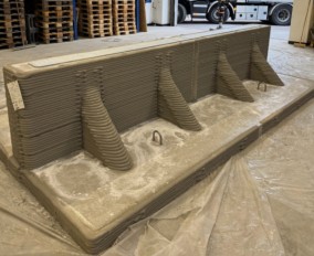
Figure 1: Schematic diagram of sheet pile wall with anchor block arrangement (not to scale).The contractor appointed on site was already implementing reusable sheet pile sections (AU-20) of 14.0 m height. Keeping in mind the importance of construction economics, it was decided to design a retaining wall using them. Given the site conditions and height of available sheet pile sections, it was decided after several trials to fill the soil with slope as shown in Figure 1, with top level of sheet pile at +10.0 m DMD and 4.5 m free height of sheet pile above the ground, increasing to 7.5 m upon completion of excavation on the right side. This resulted in lateral deflection of >100 mm at the free end of the sheet pile, which is the least amount of deflection out of all trials made. However, this was beyond the permissible limit (50 mm) as per local guidelines. To control the lateral deflection of sheet piles, it was then decided to design an anchorage system. As the contractor on site already possessed cubical concrete blocks of 1.0 m size, it was decided to use them as anchor blocks as shown in Figure 2 to control the deflection. The design of the anchorage system primarily involves the spacing of blocks, which indirectly depends on the pullout capacity of the anchor block. Pullout capacities of anchor blocks were initially determined analytically, and thereafter numerically. Figure 2: Anchor blocks behind sheet pile wall to control deflection
Analytical Approaches - 2D and 3D
The pullout capacity of anchor blocks in the 2D approach was analytically calculated using methodology based on Rankine, Coulomb, and Log Spiral theories, which is commonly used by U.A.E. geotechnical engineers. After performing the necessary calculations, the allowable pullout capacity of anchor block was found to be 123 kN after considering a safety factor of 1.5, which is too conservative according to our previous experience on similar works. This resulted in either the requirement of large-size anchor blocks, or they would need to be placed very closely to meet the pullout capacity requirement.
Hence, an attempt was made to calculate the pullout resistance of anchor blocks considering 3D effects which are closer to reality. In most cases, analytical solutions are limited to 2D with a sufficient factor of safety. This is primarily due to complications involved in formulating analytical equations considering 3D effect.
However, analytical calculations considering 3D effects were made. Upon performing calculations, the revised allowable pullout resistance of anchor block considering 3D effects increased from 123 kN (in 2D) to 285 kN after considering a safety factor of 1.5. This increased the pullout resistance by 2.3 times when 3D effect was considered and resulted in increased spacing of anchor blocks.
Yet assumptions inevitably exist in formulating any mathematical expressions for engineering problems, specifically while considering 3D effects. Hence, to verify and confirm those results obtained by analytical methods, simultaneous numerical analyses were carried out using PLAXIS, and details pertaining to it can be seen in the following sections.
Numerical Approaches - 2D and 3D
Pullout capacities of anchors were calculated using numerical 2D and 3D approaches considering plane-strain problems and volumetric modeling using the geotechnical finite element analysis (FEA) software PLAXIS.
2D Finite Element Analysis
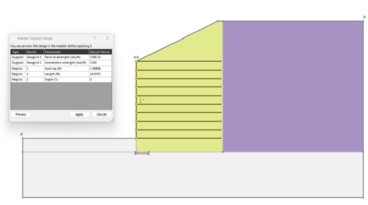
In this approach, compacted fill and concrete anchor block were modelled as plane-strain elements (see Figure 3). Compacted fill was defined using the Mohr-Coulomb material model. For concrete, a linear elastic material model was adopted in the analysis. An interface element was defined between block and compacted fill with Rinter= 0.67. Analysis was conducted in three phases:
Phase 1: In-situ stage where Ko procedure was used to initialize stress in the model.
Phase 2: Blocks, along with interface elements, were activated in the model.
Phase 3: Pressure load was activated.
Figure 3: 2D model of numerical analysis along with a load displacement curveA pressure load of 500 kPa was applied on the block. Ultimate pullout load vs. horizontal displacement was plotted (see Figure 3) to calculate pullout resistance based on serviceability criterion that limits the horizontal movement to 10 mm, i.e., 1% of a block’s height. The ultimate pullout load corresponding to a limiting movement of 10 mm was 246 kN. Accordingly, the allowable pullout resistance was 164 kN after applying 1.5 as the safety factor.
3D Finite Element Analysis
3D finite element analysis (see Figure 4) was carried out with compacted fill and concrete anchor blocks were modeled as volumetric elements with interface elements (Rinter=0.67) defined between the block and compacted fill. A phase construction sequence followed in the 3D model was the same as the 2D model, with center-to-center spacing between blocks as 2.25 m.
Figure 4: 3D model of numerical analysis along with load displacement curveA pressure load of 1000 kPa was applied on the blocks. The pullout load vs. horizontal displacement was plotted (see Figure 4) to calculate the corresponding pullout resistance based on serviceability criterion that limits horizontal movement to 10 mm, i.e., 1% of a block’s height. The ultimate pullout load corresponding to limiting movement of 10 mm was 436 kN. Therefore, the allowable pullout resistance was 291 kN after applying 1.5 as the safety factor, which is very close to the value (285 kN) obtained in the analytical approach after considering the 3D effect.
Comparison of Analyses
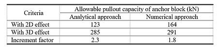
Results obtained from both analytical and numerical approaches are summarized in Table 1.Table 1: Pullout capacities of anchor blocks in analytical and numerical approaches
In both analytical and numerical approaches, a significant increment in anchor block pullout capacity was observed after considering the 3D effects over those capacities obtained by considering 2D analysis. As a result, this helps in avoiding underestimation of an anchor block’s pullout capacity and thereby aids in the optimization of anchor block design. In addition, it was promising to note that pullout capacities obtained after considering the 3D effects from both approaches are very close in their magnitudes. 3D analysis simulates the reality with lesser assumptions and hence brings significant optimization to the design compared to 2D analysis, irrespective of the complexity and time involved in 3D analysis. Undoubtedly, performing 3D analytical calculations is a tedious work and PLAXIS made our job easy to to handle this.
During the construction phase, lateral deflection measurements at the free end of sheet piles at different locations were made to identify for any unwanted and excessive lateral movements. Out of all the observations made from start to end of construction, at no time were deflections more than 30 mm, which came well within the permissible lateral deflections (50 mm) according to local guidelines. This is mainly due to the inclusion of anchor blocks behind the sheet pile wall to control excessive deflections (>100 mm) noticed during initial phase calculations without any anchoring system. Thus, anchor blocks were found promising in controlling lateral movements in sheet piles.
Conclusion
The analysis performed using PLAXIS 3D helped in overcoming the underestimation of pullout capacity of anchor blocks and thereby optimizing the design of anchor blocks. In addition, 3D numerical analysis helped in properly simulating the given problem by taking into account group effects of blocks and block-soil interactions and thereby incorporating lesser assumptions.
Acknowledgements
The authors would like to thank Emaar Development – The Lagoons Phase One L.L.C. for their support and cooperation. Special acknowledgments are extended to Eng. Abdulqader Abusoud, Eng. Arif Ustadi, and Eng. Omar Bustami from Emaar Development.
The following was prepared by a Bentley Expert and first presented by Virtuosity.
Authors
Ramesh Vandanapu Assistant Professor in Civil Engineering, Amity University, Dubai, United Arab Emirates Akash Sharma Geotechnical Engineer, Fugro Geoconsulting, Dubai, United Arab Emirates Marwan Alzaylaie Senior Manager - Geotechnical, Dubai Development Authority, Dubai, United Arab Emirates
Geoengineer.org uses third party cookies to improve our website and your experience when using it. To find out more about the cookies we use and how to delete them visit our Cookies page. Allow cookies