How To Efficiently Speed Up Mesh Generation Sponsored
PLAXIS 3D is a very powerful tool that can provide extremely valuable information to geotechnical engineers, but did you know there are some insider tips that can help you save time? Here is some useful information on how to efficiently use PLAXIS 3D to confidently move forward in creating complex 3D mesh and optimally and successfully perform analyses.
Understanding the PLAXIS modeling and meshing workflow
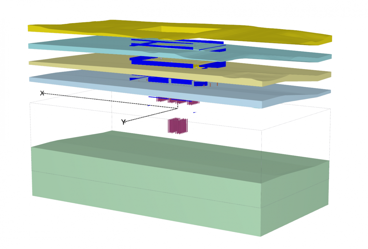
PLAXIS 3D uniquely addresses geometry creation in a very particular and unique way as it offers two independent geometry definition environments:
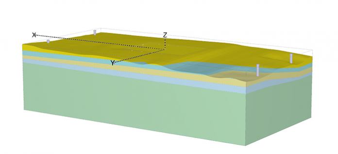
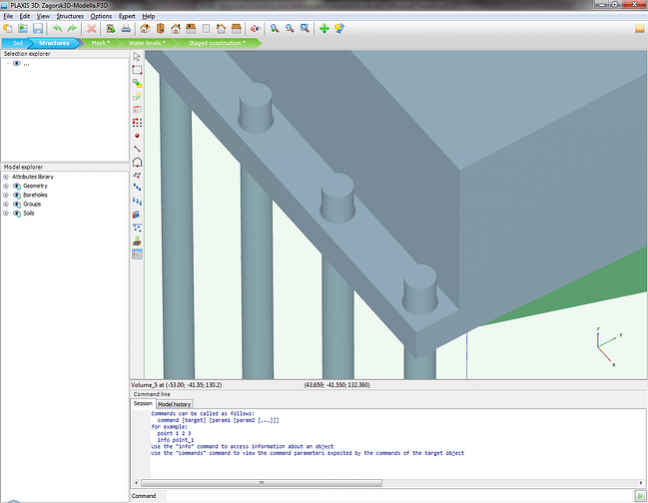
- One for soil (Soil geometry mode): Representing soil stratigraphy before project construction starts (see Figure 1a)
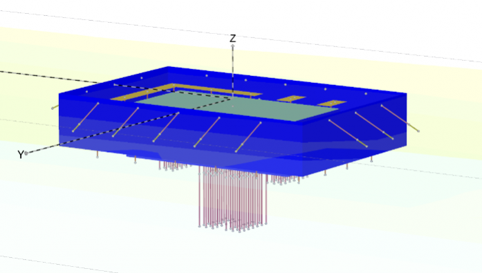
- One for structures (Structure geometry mode): Displaying all project-related geometry (see Figure 1b)
From a geometry definition point of view, this is very convenient. You don’t have to worry about geometry connectivity among any geometrical components placed in the model. The PLAXIS 3D geometry kernel engine automatically takes care of performing intersection and re-clustering (i.e., eliminating overlapping objects) of all constitutive geometrical components (see Figure 1c).

Learn more about PLAXIS 3D
Some good habits
The quick generation of an optimized mesh always starts with some simple considerations, which we would like to summarize here.
ONLY MODEL WHAT IS NECESSARY
The first tip is to model and mesh only what is necessary and relevant for your design. For instance, always start identifying symmetry conditions and make use of then. This could be plane symmetry for excavation, cyclic symmetry for quay wall, etc.
Please take special care to note the introduction of any small details. The presence of any geometry object whose dimensions are less than 1/100 of the overall model dimension should indicate that perhaps the model dimensions are too large, or that the extremely small object might not need to be considered (see Figure 3).
PREVENT SMALL GAPS AND OVERLAPS
Many intersection and meshing issues are caused by small gaps or overlaps in the model. Often, users are unaware of these gaps or overlaps because they assume that contiguous objects are properly connected to one another.
This is why it is fundamental to create new geometrical objects in relation to existing ones (using the array command, snap command, or combination of the Decompose tool followed by an extrusion operation) rather than simply defining objects in an absolute manner with global coordinates irrespective of existing objects.
In this context, PLAXIS 3D provides a powerful set of diagnostic tools that help you to create “clean” model geometries:
- The Tabulate command will display all properties of the specified geometry objects
- The Echo command will provide exact coordinates of specified geometry objects
- The Check Geometry command will perform a check regarding overlapping or adjacent geometry objects and return a list of items with their relative distances. The check is limited to a user-defined tolerance beyond which geometry checks will not be performed.
ALWAYS EVALUATE MESH QUALITY
Mesh quality assessment can be performed in the PLAXIS output program from any generated mesh. The element aspect ratio can be evaluated for any element with the ability to easily identify and locate the worst quality shape element.

IS CAD IMPORT ALWAYS THE BEST OPTION?
At first, importing the geometry from a CAD model often appears to be an interesting option. Novice PLAXIS 3D users usually find themselves much more proficient at creating a geometry in a modeling environment they are already familiar with, or simply (and this is the most common case) because the CAD model already exists!
However, there are a few things users might not be aware of when importing CAD geometry in PLAXIS 3D:
- The CAD model might contain a significant quantity of irrelevant objects (construction lines, dimensions, annotations, large amount of insignificant details, etc. ) that would need to first be properly identified in the PLAXIS modeling environment and then deleted.
- CAD geometries are meant be used for drawing, drafting reports, or calculating quantities …. not being meshed. Meshing requires a much higher level of accuracy and contiguity of the geometry definition. For this reason, any imported CAD geometries must systematically undergo a thoughtful diagnosis with any possible associated repairing operations before being tentatively considered and meshed. Any remaining imprecisions in the geometry will surely lead to either intersection or meshing issues.
Because of this, we highly recommend the use of CAD import only for geometries that simply cannot be created natively in PLAXIS 3D or that would require excessive re-modeling time. In many cases, it is much easier and significantly faster to recreate the geometry natively from scratch rather than trying to import it from a CAD package.
Pushing the boundaries
As previously stated, PLAXIS 3D is an extremely powerful tool that enables you to create simple geotechnical models quite quickly once you become familiar with the modeling environment and workflow. It is important to follow the proper methodology to save time when creating more complex geometry and associated meshes.
AUTOMATION AND SCRIPTING
Complex models often contain a significant number of objects. Using automation technology can be enormously helpful by helping you avoid errors and save time.
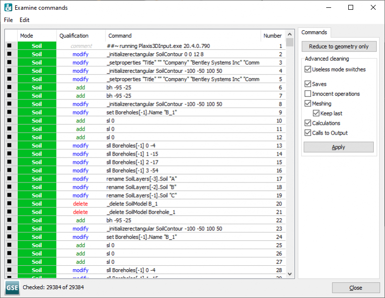
PLAXIS offers a simple command-line mechanism that is easy to access. The tool reads a command file to help you generate a model. Note that such a command history is systematically generated during any model creation in PLAXIS, offering even greater accessibility of the technology (see Figure 5). In combination with a Microsoft Excel spreadsheet, where formulas can be used and corresponding PLAXIS commands written, this has proven to be a very efficient means to speed up and reduce the number of possible errors and inconsistencies in geometry definition.
PARTITIONING
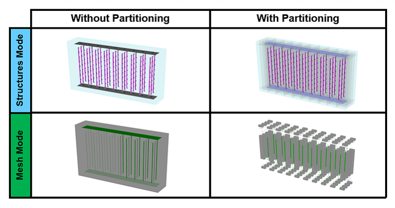
A complex geometry can always be subdivided into a set of simpler topological shapes. This is basically what lies behind the word “partitioning.” This process requires the definition of additional geometry objects (mostly “slicing” surfaces) for the purpose of introducing additional but simpler geometrical objects to the mesher and therefore reducing the number of “topological” constraints. (see Figure 6). This technique has proven to:
- Systematically result in successful meshing
- Significantly reduce mesh generation time especially when EMR (enhanced mesh refinement) option is not selected
- Offer more control over mesh density in the model itself
Partitioning is not mandatory. It does not bring additional value to standard or relatively simple geotechnical models. However, partitioning has proven to be useful for complex geometry and lengthy meshing processes, leading to a considerably less dense and more affordable mesh compared to models with no partitioning.
Learn more about PLAXIS 3D
Discover the Plaxis Productivity Strategies Blog
Watch LinkedIn Live Session, by Richard Witasse, sharing tips for speeding up mesh generation, as well as calculation time.

Source: How To Efficiently Speed Up Mesh Generation
Want to read more like this story?

PLAXIS 2023.2 New release is out!
Sep, 07, 2023 | NewsThis latest release solidifies Seequent's Connected Geotechnical Workflow, reducing the need for du...

New major release PLAXIS CONNECT Edition V22.00 is out!
Jan, 28, 2022 | NewsPLAXIS V22 brings a major overhaul to the data structure of the material database and a more flexib...

New releases: PLAXIS CONNECT Edition V22 Update 2 is out!
Oct, 13, 2022 | NewsWith the latest release of PLAXIS 2D, PLAXIS 3D, and PLAXIS Monopile Designer, Bentley continues to...

Why Run PLAXIS 3D Analysis?
Jun, 07, 2021 | NewsMost geotechnical engineers use FEA software packages for their geotechnical design. It is especial...

New release PLAXIS CONNECT Edition V22 Update 1 is out!
May, 19, 2022 | NewsIn this latest minor release for PLAXIS 2D, PLAXIS 3D and Monopile Designer Bentley Systems introdu...

New release of PLAXIS CONNECT Edition V20 Update 1
Jan, 20, 2020 | NewsPLAXIS CONNECT Edition version 20.0 includes streamlined user experience, increased performance an...

Bentley releases new PLAXIS versions
Jun, 15, 2020 | NewsBentley is happy to announce the release of new PLAXIS CONNECT version (Edition V20 Update 3), incl...

GeoStudio 2022.1 new release is here!
Oct, 27, 2022 | NewsIn the latest GeoStudio version, you’ll notice improvements to speed up your geotechnical 3D workfl...

PLAXIS – From Concept to Construction
Mar, 03, 2022 | NewsImporting geometric and stratigraphic data to PLAXIS 3D Any infrastructure project begins with a t...
Form
Looking for more information? Fill in the form and we will contact Bentley for you. Alternatively, you can visit Bentley's website and speak with a Bentley Geotechnical Expert.
On This Day
August 2nd 1754
READ MORE
Related Video

Trending
Seven Frequently Asked Questions about Helical Piles

Block caving: A new mining method arises

Categories of isolated foundation footings
Maharashtra's longest road tunnel to be completed soon

Carnian Pluvial Episode: That time when it rained for 1-2 million years
Nepal’s Himalayan settlements face escalating flood and landslide threats