As growing human populations settle more and more in low-lying coastal areas and near waterways, flood protection systems are becoming increasingly important engineered structures. Threats from sea-level rise as well as extreme weather events both appear to be here to stay, and provide greater stresses on these structures. In order to provide strong, stable levee systems that also preclude leakage of (possibly contaminated) water, geosynthetic materials are becoming a standard technique for constructing levees. Geosynthetics are polymer plastics utilized in geoconstruction projects, and include a wide variety of types, materials, and functions, as will be described later. As we examine geosynthetic usage in levees, we focus our attention primarily on two functions: to provide reinforcement for structural stability against flooding events and to prevent leakage through the levee, thus not only leading to a more durable structure, but also preventing the potential spread of water contamination. Let us turn to a famous case to demonstrate the first function.
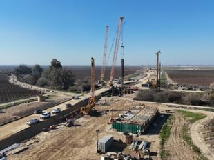
The LPV 111 levee in New Orleans, Louisiana, was first built in 1955 and subsequently raised in the 1970s to a height of 17 ft (Kelsey 2020). Following Hurricane Katrina in 2005, LPV 111 suffered major scour damage and required repair to protect against future storm surges. Therefore, in 2010-11, engineers worked to repair a 5.2 mile stretch of the levee, raising it to a new height of 27 ft. To accomplish this feat in a shortened timeline, 450,000 square yards of polyvinyl alcohol (PVA) geogrids were utilized to distribute load over deep soil mixed piles (see Figure 1). After evaluating several other alternatives for carrying load--T-walls were too expensive, lightweight fill would have been too risky in the event of another flood, staged construction with wick drains would have taken too long to cause consolidation, stability berms would encroach on surrounding wetlands, and stone columns would not be able to be built in the extremely soft soils on site--deep soil mixing was finally selected for the project. Deep soil mixing essentially consists of drilling down a specified depth to firmer soil and mixing in cement to create an unreinforced pile. In this case, depth of piles varied substantially, but 50 ft is representative of average conditions. At the time of construction, this project represented the largest deep soil mixing project in the world, totaling in at 1.7 million cubic yards of material mixing! The geogrids themselves were HUESKER Fortrac 400MP models, manufactured from creep-resistant yarns and typically used for railway support, slope stabilization, and other similar applications. They can withstand a variety of pH conditions anywhere between 2 and 13, a key criterion for the high pH soil environment at the site, and show no more than 5% maximum elongation over a 100 year design life. These characteristics, along with the decreased number of piles that would be needed, made the HUESKER model a good choice for providing geosynthetic reinforcement to the levee. As a result of geosynthetic usage, fewer piles were required to be mixed, offering savings in cost, time, and factor of safety.
Figure 1: Rolling Out of PVA Geogrid at LPV 111 Levee Repair Project in New Orleans (Kelsey 2020)
Leakage Prevention
Though reinforcement is certainly a popular function for geogrids, controlling internal leakage and drainage offers another area for geosynthetics to prove their worth. Numerical, centrifuge-based, and other models have been developed to assess leakage levels for varying conditions and geosynthetics (Saran & Viswanadham 2018). The primary phenomenon of interest is the buildup of pore pressures within the levee: adequate drainage materials, such as coarse-grained soils or geosynthetics, are necessary to prevent pressure buildup, which leads to reduced effective stresses needed to keep the levee structurally sound. Compared to sand drainage layers, geotextiles and geocomposites can offer lower costs, better quality control, and easier installation. Unlike sand, which causes the phreatic surface to be confined within the levee itself due to a high permeability region, the synthetic materials cause the surface to gradually migrate towards the levee toe, which can be attributed to the blocking of geotextile pores by fine soil particles once seepage begins (see Figure 2). Study results indicate that, as expected, proper drainage reduces the risk of catastrophic failure, and that sands, while effectively reducing pore pressure, do not avert collapse for as long as geotextiles do. Another option to combine the benefits of the two materials is the sandwiched structure, or a geotextile placed within a sand layer. Though further testing is needed in this domain, sand layer thickness may be reduced by around 25% in this setup relative to the no-geotextile scenario, thus providing cost savings to counter the effect of an added geotextile.
Figure 2: Model results of a) no drainage, b) sand drainage, and c) geotextile drainage. u/γH is a measure of pore pressure, ts is the time to steady state seepage, and FS is the safety factor. Both sand and geotextile drainage systems reduce pore pressures, though the former does so to a greater extent. Geotextiles provide a longer time for the seepage equilibrium surface to be reached, and both lead to a safety factor greater than one, unattainable in the no drainage levee (Saran & Viswanadham 2018)
Given the advantages of implementing geosynthetics into levee design, there still exists a choice of where to place the geosynthetic for maximum benefit. One important division can be observed between what are known as geosynthetic-reinforced soil (GRS) and laminar drain reinforcement (LDR) levees (Kurakami & Nihei 2019). The former consists of a geogrid connected to a concrete panel on the back side of the levee in order to resist overflow. However, once the phreatic surface reaches the back slope, instability results and failure can be sudden. The LDR levee combines the advantage of the GRS in resisting overflow with infiltration protection through the use of a sand or gravel drainage layer through which the geogrid runs (see Figure 3). Drainage prevents excessive pore pressure buildup, giving the levee greater resilience to high hydraulic heads (see Figure 4). Other LDR benefits include air ventilation through the drainage layer, prevention of suction of the levee body due to the presence of a geo-fabric, and stronger connection of the concrete panel to the levee. These benefits must be weighed against the cost of implementing a drainage system, the additional geosynthetics needed, constraints in constructability, and so forth.
Figure 3: Schematic of an LDR levee: drain layer formed of coarse soil or cobbles lowers the water table surface within the levee. Geosynthetic materials, usually a geogrid and a non-woven fabric, are run through the drainage layer and along its boundary, forming a separation between it and the rest of the levee body. The geogrid also connects the concrete panel to the levee, providing strength against outflow during flooding events (Kurakami & Nihei 2019)Figure 4: Phreatic surface at different times in a) GRS and b) LDR levee models. As can be observed, the latter’s drainage system causes the phreatic surface at the levee toe to drop significantly relative to the GRS case. Because of this difference, time to levee failure is substantially increased in the LDR levee (Kurakami & Nihei 2019)To determine the difference between GRS and LDR levee performance under flood scenarios, Kurakami and Nihei ran models on four different levees: basic armored, GRS, LDR with a 20 cm long geogrid, and LDR with a 10 cm long geogrid (Kurakami & Nihei 2019). Based on their results, summarized in Table 1, the LDR levee provides a significant functional advantage over armored and GRS types, requiring more than 50% more time to fail compared to these alternatives. Moreover, the 20 cm geogrid nearly doubles the time to fail compared to the 10 cm geogrid, making geosynthetic dimensions a key design consideration for LDR levees. It was noted that concrete panel outflow occurred at a 3 cm gap for the armored case, while for all others it took 7-20 cm, reinforcing the conclusion that geosynthetics are useful both for leakage prevention and for strength reinforcement in levee design.
Table 1: Failure Results for Various Levee Designs (Kurakami & Nihei 2019)
Basic Armored
GRS
LDR (20 cm)
LDR (10 cm)
Time to Failure (min)
87
102
150*
150*
Time to Failure without Scour Protection (min)
112
57
Max Concrete Panel Gap (cm)
3
16
19
19
Time Between Gap Occurrence and Panel Outflow (min)
This section gives an overview of types of geosynthetics. Geosynthetics (GS) are synthetic polymeric or natural materials in the form of strips, sheets, or structures. They have the advantage of being easy to transport, thus making the construction efficient and eco-friendly. Geosynthetics perform 5 essential functions in construction: separation, reinforcement, filtration, drainage, and containment. Different types of geosynthetics have different merits when applied in construction. Table 2 provides an overview of the primary function of geosynthetics (Dashore, 2016).
Table 2: Primary Function of Geosynthetics (Dashore, 2016)
Type of Geosynthetic
Separation
Reinforcement
Filtration
Drainage
Containment
Geotextile
✓
✓
✓
✓
Geogrid
✓
Geonet
✓
Geomembrane
✓
Geosynthetic Clay Liner
✓
Geopipe
✓
Geoform
✓
Geocomposite
✓
✓
✓
✓
✓
This page will discuss geotextiles, geogrid, and geomembrane in detail since they’re the most frequently used geosynthetics for levee construction.
Geotextiles
Figure 5: Example of Geotextiles (Nicholson, 2015)Geotextiles are one of the two largest groups of geosynthetics in terms of volume and applications in construction. They are permeable synthetic fabrics typically made from polypropylene and polyester rather than natural ones such as cotton, thus making them less susceptible to biodegradation. Polypropylene has a specific gravity of 0.9, which is lighter than water. The material is considered to be strong and durable. On the other hand, polyester is denser than water, and it has excellent strength and creeps properties (Lawson, 2008).
Table 3: Properties of Common Polymers Used in Geotextile (Lawson, 2008)
Geotextiles can be used for separation, filtration, drainage, reinforcement (Wu & Yao, 2020). Geotextiles can separate two kinds of materials, avoiding mixing and losing integrity to the structures. Geotextiles can be used for separation between subgrade and stone base in unpaved and paved roads and airfields, between subgrade in railroads, between sidewalk slabs, etc. Separation is illustrated in the following figure. The separation function of geotextiles can effectively prevent pumping effects created by dynamics.
Figure 6: Separation Function of Geotextiles (Wu & Yao, 2020)Another function of GT is filtration. They have positive permeability and air permeability, thus they can be placed in soil to allow liquid to pass through and discharge. This helps soil conservation and avoids suffusion. As an example, geotextiles are used to prevent soil particles from migrating and infiltrating drainage aggregates or drainage pipes, while maintaining the normal operation of drainage systems; laying geotextiles under a riprap protective layer and other protective materials on coasts and riverbanks can prevent soil erosion and riverbank collapse (Nicholson, 2015). The following figure shows the mechanism of suffusion and a comparison with and without geotextile.
Figure 7: Filtration Function of Geotextiles (Wu & Yao, 2020)By placing geotextile in the interior of the soil, it combines with soil to form reinforced composite soil, significantly increasing the strength and deformation performance. In the meantime, it also acts as a barrier and erosion protection. Geotextiles can also be used as drainage channels due to favorable water conductivity. It collects water from soil structures and discharges along with itself slowly. Illustrated in tfollowing Figure 8.
Figure 8: Drainage Function of Geotextiles (Wu & Yao, 2020)
Example application of geotextile in levee (Wu & Yao, 2020)Geotextile versatility provides a wide range of civil engineering applications for roads, airfields, railroads, embankments, retaining structures, reservoirs, canals, dams, bank protection, coastal engineering and construction site fences or geotube. For example, specific applications include mass-gravity revetment and dyke structures, dewatering of waste and contaminated sediments, offshore disposal of contaminated soil and sediments, etc. In our levee case, geotextiles are often used for reinforcement and drainage.
Geogrids
Geogrids are polymeric materials formed by extrusion, weaving, or welding to form open aperture products of varying strength, strain, and load-carrying capability for applications of soil reinforcement. Based on which direction the stretching is done during manufacturing, geogrids are classified as either uniaxial geogrids or biaxial geogrids (S K, 2016). The following figure is an illustration of typical Uniaxial and Biaxial geogrids
Figure 9: Example of Geogrids (Brown, 2007)The biaxial grids were identified using a code such that a ‘45–65’ grid had a nominal tensile strength of 45 kN/m, based on the standard test used for standardization and quality control purposes, and a nominal aperture size of 65 mm. All the geogrids have square apertures.
Geogrids are commonly used to reinforce sub-bases or subsoils below roads, as well as retaining walls or other structures. The usage of geogrids in retaining wall construction is in the area of soil backfills. Holding the soil together will help in stable retaining wall construction.
Reinforcing with geogrid makes the whole structure behave as a single mass, thus increasing structural integrity. This helps in confining backfill as well as helps in distributing the loads. The geogrids solve the problems with soft backfill or sloping ground (Mandavkar & Weldu, 2019).
Figure 10: Typical Cross Section of Reinforced Soil Slope (RSS) Using Geogrid (S K, 2016)Now, geogrids are used in many other structures like dams and pavements due to their ability to redistribute load over a wider area, high holding capacity, high tensile strength, and eco-friendly nature. Geogrids have other advantages including ease of construction, optimize land utilization, high availability, high resistance against environmental influences, etc. The versatility of the material in nature provides versatile applications in geotechnical engineering.
Geomembranes
Geomembranes are flexible and watertight polymeric membranes manufactured with a wide range of polymers such as plastic, elastomers, and blends of the polymers. They are thin membranes, and the thickness is often 0.5 mm or more. The material has effective permeability or hydraulic conductivity on the order of 10-10~10-13cm/s, and such low permeability appears a solution to seepage and leakage problems, provides a function of containment.
Figure 11: Example of GeomembranesGeomembranes are used in applications wherever a hydraulic barrier is needed in construction. They are most commonly used as primary and secondary containment for hazardous materials, preventing leakage from spills. Figure 12 shows the typical installation of geomembrane (Cargo-Guard, 2019).Figure 12: Geomembrane Installation (Cargo-Guard, 2019)The material needs to be strong enough to provide long-term containment against UV exposure and extreme weather conditions. What material used decides the age and performance of the membrane. Major properties of geomembrane include: Firstly, physical properties as manufactured including thickness, density, melt flow index, mass per unit area, vapor transmission. Secondly, mechanical properties being tested on including tensile strength, tear resistance, puncture resistance, etc. Thirdly, endurance to UV light, radioactive degradation, thermal, chemical, etc. Lastly, the lifetime of the material does degrade slowly, we test lifetime by accelerated testings including stress limit testing, rate process method, Hoechst multiparameter approach, etc. The cost of the material lies around 2 $/m2which is comparatively higher than other geosynthetics.
The design and construction of levees and embankments have numerous factors to be considered, from overall purpose and functionality to location, proximity considerations, and fill material type. These factors may vary from project to project, but an overall sense of steps and procedures should be followed based on past successes. Generally, levees and embankments are comprised of pervious and non-pervious, or coarse-grained and fine-grained, soils, each having a specific purpose. Where pervious materials are mostly easier to move and construct with, fine-grained soils, normally clays in this regard, provide the benefit of having a very low hydraulic conductivity.
Embankment Geometry
When it comes to the design elements of a levee or an embankment, there are several factors that need to be taken into consideration, namely: the foundation, it’s adequacy, which is directly related to soil type; the fill material used to construct the bulk of the levee, whether it be compacted or hydraulically placed fills; and the composition of the impermeable core. All of these factors are directly affected by the overall purpose, and how the embankment is intended to function. The main components of a levee are the waterside slope, which is the side that is in direction contact with the retained body of water; the landside slope, which is the side opposite of the retained body of water, and is usually dry; and the embankment crest, which is the plateau-like feature of the levee, and is often designed with a functional width. The elevation of the levee above the ground surface should take into account an allowance for varying retained water heights. These components, and how they fit together to configure a levee, can be seen in Figure _, below.
Figure 12: Typical Levee/Embankment ConfigurationThe final configuration of a levee is mainly influenced by the material it is constructed from, but, more importantly, the material it is founded on. The material and effort used to construct the levee has an influence on the geometry. In areas where space is limited, such as areas of urban development, compacted material allows for steeper slopes, as compared to placement by hydraulic methods. Hydraulic methods generally involve loose placement of more pervious materials, such as sands, resulting in shallower slopes. Oftentimes, geosynthetics are used to reinforce embankment slopes to achieve greater slope angles, especially for situations where adequate fill material is difficult to import; however, for situation where geosynthetics are not implemented for stability, the steepest allowable slope is one vertical unit to two horizontal units (1V:2H). This slope angle usually involves revetment in the design, or the armoring of the waterside slope with a layer of what is referred to as riprap, or large, angular rocks. Where this is the case, a geogrid or geotextile is used as a barrier between the underlayer and the embankment soil. An example of this can be seeing in Figure _, below.
The levee crest, as previously mentioned, takes into consideration the potential for variable retained water heights. This concept is called freeboard, which, more recently, has gravitated toward a risk-based analysis to account for destabilizing hazards, such as: underlying material settlement, shrinkage, geologic subsidence, and construction tolerances. A risk-based analysis is a deterministic way to weigh the physical properties of the levee and foundation materials, along with site-specific geologic features, and how they will respond. This analysis also serves as a means to include hydraulic uncertainties to establish a nominal elevation. The width of the embankment crest is largely determined by access needs. These needs can be for maintenance vehicles, emergency vehicles, and even earthmoving equipment, which often have a minimum requirement of 10 to 12 feet. This, however, is usually decided by the agency who will be responsible for the operation and maintenance of the structure.
Components
Foundation
The foundation of a levee often requires a minimum level of preparation before construction can begin. The general process involves clearing and grubbing of the plan area, which is the complete removal of any obstructional objects, including organic matter, at the ground surface; stripping, or the removal of low growing vegetation and the upper 6 to 12 inches or organic topsoil; and the proper disposal of the removed material. An explorational trench is then dug to determine if there are any undesirable features or buried objects located along the alignment of the levee. The dimensions of the trench vary depending on the underlying soil and the overall configuration of the embankment; however, a minimum depth of 6 feet is required, unless the height of the levee is less than 6 feet, in which case the trench depth should match the height. Trenching, in this regard, allows for inspection of seepage channels or other potentially destabilizing site conditions. As a final foundation preparation measure, the surface where the fill material is to be placed should be scarified, or broken up, to a depth of no less than 6 inches. This is to ensure a strong bond between the foundation soil and the placement material, reducing the potential for a plane of weakness at the interface. The foundation soil should be kept dry before scarification, and scarification should occur just before the first lift of the fill material is placed. Any soft or organic material found within the foundation plan area should be removed and replaced with more competent, compacted soil.
Fill Material
Coarse-grained materials have the benefit of providing stability by their higher unit weights; however, the trade-off is that water is able to flow freely through their respective void space. Since this is the case, a high permeability material needs to be balanced with that of a low permeability material, i.e., a fine-grained soil, or a clay-like material in this regard. The low permeability layer, which is often used at the core of an embankment, in tandem with the underlying foundation, creates longer flow paths for the permeating water. With the mixed-use of fill material type, utilizing their respective benefits, potentially destabilizing hazards, such as settlement, global instability, external and internal erosion, and tension cracking, can be mitigated through proper design. In an attempt to design a more efficient structure, and to further aid in mitigating failure, different types of geosynthetics can be used. The most common type of geosynthetic used in levee and embankment design is geogrid. Geogrid is generally designed to extend a factor of the levee height into the levee, and is often laid out in several layers throughout the structure height.
Compacted Fills
As previously mentioned, the type of fill material, along with the level of compaction effort applied, will ultimately dictate the embankment geometry. Semicompacted fills are usually fine-grained borrow materials that are far more wet of their optimum water content and are used where the design requires much shallower slopes for stability. Uncompacted fills are generally highly organic borrow materials that, like semicopacted fills, are used for shallow slope construction. When the foundation of the levee has adequate strength, and when space requirements are a factor for design, compacted fill construction would then observe the procedures for earth dam building.
Hydraulic Fills
Hydraulically placed soils are mostly coarse-grained, pervious materials. Since levees that are constructed of hydraulic fills generally have low densities and large plan areas, they are very susceptible to liquefaction. Hydraulic fills also tend to erode when overtopping occurs, or when a non-pervious layer cover layer is breached. This type of fill is mostly used for stability berms and seepage berms, but not normally for embankments; however, where human life is not threatened by levee failure, or where an embankment includes impermeable core, hydraulic fills can be used.
Impermeable Core
The impermeable core portion of a levee is often a structure composed of fine-grained, non-pervious soil located at the very center of the levee and anchored into the foundation material. The intention of having an impermeable core, along with the underlying foundation, is to create a longer flow path for the permeating water. Although the clayey soil used has the benefit of low permeability, it is prone to destabilization due to surface cracking and internal erosion. This is another good opportunity to include geosynthetics into the design. In this specific case, a top layer of geogrid has the potential to minimize the extent at which surface cracks could form, as well as a layer of geotextile to act as a filter to prevent internal erosion.
Much of levee design, including the use of geosynthetics, is rightly concentrated on structural strength requirements to prevent catastrophic breaches and flood events; however, there are several environmental consequences that can arise from improper design and construction as well. Levees principally fail due to overflow, infiltration, and erosion; these three failure modes each carry concerns related to contamination of water bodies and human exposure (Dortch et al. 2007). For example, the presence of heavy metals and organic compounds in floodwaters could threaten ecosystem health, and moreover, human health, especially in those water bodies used by humans for drinking water or agricultural production. Bacteria present a biological concern for similar reasons, and turbidity levels could be problematic for drinking water systems. Finally, salinity can present an issue, particularly in coastal and marine environments, when salty or brackish waters are allowed to mix with freshwater, whether surface or underground.
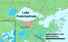
Figure 14: Map depicting Lake Pontchartrain just north of New Orleans, Louisiana, and west of the Gulf of Mexico. Following the storm surges of Hurricane Katrina in 2005, Pontchartrain served as a receptacle for the massive amounts of floodwater devastating the city. High levels of floodwater pumping lead to increases in certain contaminants in the lake (https://upload.wikimedia.org/wikipedia/commons/thumb/c/c0/Lake_Pontchartrain.png/240px-Lake_Pontchartrain.png. Accessed April 24, 2021)Again, let us use Hurricane Katrina to gain an understanding of the contamination possible due to levee failure. Following the hurricane’s storm surge, New Orleans was forced to pump flood waters out of the city into nearby marshes and Lake Pontchartrain, shown in Figure 14. Normally, storm water alone is pumped, and the differences between this baseline scenario and the actual scenario have been analyzed using numerical modeling coupled with field data and regulatory standards (Dortch et al. 2007). Contaminants studied include trace metals like arsenic (As) and lead (Pb), organics like benzo(a)pyrene (BaP) and 1,1-dichloro-2,2-bis(p-chlorophenyl)ethylene (DDE, a degradation product of the better known DDT), and fecal coliform bacteria (FCB). Results from Dortch et al. indicate that FCB exceeded standards in both baseline and actual conditions, As and Pb were under in both, and BaP and DDE, though normally compliant, were exceeded under actual conditions. It was observed that, “incremental increases above pre-Katrina benthic sediment [contaminant] concentrations are about a factor of 10 greater with dewatering of the floodwaters than with dewatering of storm water without flooding” (Dortch et al. 2007). However, contaminant concentrations in the water itself were not greatly affected by the flood waters; also, metals and long-life organics (such as DDE) have higher, more stable baseline levels, making the incremental changes relatively small. Still, contaminant increases in lake and marsh sediment can bear important repercussions not only for wildlife and ecosystems, but also for human beings when sediment is suspended in the surface water or contaminants are able to enter and travel through groundwater aquifers. Ensuring adequate safety factors against levee leakage and overtopping, especially through the usage of geosynthetics, can largely reduce these risks.
Kurakami, Y., & Nihei, Y. (2019, August 25). Resistance of laminar drain reinforcement levee against overflow erosion. Retrieved April 15, 2021, from https://www.mdpi.com/2073-4441/11/9/1768
Lawson, C. R. (2008). Geotextile containment for hydraulic and environmental engineering. Geosynthetics International.
Müller, W. W., & Saathoff, F. (2015). Geosynthetics in geoenvironmental engineering. Science and Technology of Advanced Materials, 3, 034605. https://doi.org/10.1088/1468-6996/16/3/034605
Nicholson, P. G. (2015). Geosynthetics for Filtration Drainage, and Seepage Control. In Soil Improvement and Ground Modification Methods (pp. 189–207). Elsevier. http://dx.doi.org/10.1016/B978-0-12-408076-8.00008-X
U.S. Army Corps of Engineers. (2000, April 20). Engineering and Design: Design and Construction of Levees. Washington, D.C.
Wu, H., & Yao, C. (2020). Review of Application and Innovation of Geotextiles in Geotechnical Engineering. Materials. https://doi.org/Materials 2020, 13, 1774
2 COMMENTS
Jeong-Yun Won*
May, 05, 2021 It is a very thorough review of geosynthetics in controlling stability and leakage in levees and embankments. At first I felt like the authors (project participants) were the ones who performed the projects (LPV 111 and other case histories). The authors could have given the credits of the case histories and design cases to the original report, paper or other responsible parties. Proper citations could have been given to all the figures and the majority of the contents. The introduction could have included why the authors worked on this topic, how they approached this topic, methodology (read a lot of references, copy the contents, and so on), and others. A brief summary stating what the authors learned from this project or summary of the project itself would be helpful for readers. Well written project report. Go bears!
Matthew Grehm
May, 14, 2021
Thank you for your thorough comment: we have worked to make our references/citations more explicit as to bestow proper credit for intellectual property. Going forward, we will implement a structure similar to what you suggested with regards to methodology, summary, etc. And yes indeed, go bears!
Geoengineer.org uses third party cookies to improve our website and your experience when using it. To find out more about the cookies we use and how to delete them visit our Cookies page. Allow cookies
")
 no drainage, b) sand drainage, and c) geotextile drainage. u/γH is a measure of pore pressure, ts is the time to steady state seepage, and FS is the safety factor. Both sand and geotextile drainage systems reduce pore pressures, though the former does so to a greater extent. Geotextiles provide a longer time for the seepage equilibrium surface to be reached, and both lead to a safety factor greater than one, unattainable in the no drainage levee (Saran 2018)")
")
 GRS and b) LDR levee models. As can be observed, the latter’s drainage system causes the phreatic surface at the levee toe to drop significantly relative to the GRS case. Because of this difference, time to levee failure is substantially increased in the LDR levee (Kurakami 2019)")


 Using Geogrid")


")
 Edward Vaccaro


2 COMMENTS
Jeong-Yun Won*
May, 05, 2021 It is a very thorough review of geosynthetics in controlling stability and leakage in levees and embankments. At first I felt like the authors (project participants) were the ones who performed the projects (LPV 111 and other case histories). The authors could have given the credits of the case histories and design cases to the original report, paper or other responsible parties. Proper citations could have been given to all the figures and the majority of the contents. The introduction could have included why the authors worked on this topic, how they approached this topic, methodology (read a lot of references, copy the contents, and so on), and others. A brief summary stating what the authors learned from this project or summary of the project itself would be helpful for readers. Well written project report. Go bears! Matthew Grehm
May, 14, 2021Thank you for your thorough comment: we have worked to make our references/citations more explicit as to bestow proper credit for intellectual property. Going forward, we will implement a structure similar to what you suggested with regards to methodology, summary, etc. And yes indeed, go bears!
Edit Comment
LEAVE A COMMENT