Slope Inclinometers
Contents [show]
Introduction
Geotechnical instrumentation is a critical part of every construction project as it provides vital information about the in-situ behavior of the ground. Instrumentation methods highly depend on the substratum and groundwater conditions. The instruments utilized are also impacted by the design methods and the compatibility of a project.
Slope inclinometers are devices developed to monitor and measure the deformation of the subsurface. They have been widely used since the 1950s to evaluate the performance of natural slopes, embankments and retaining walls providing significant data about in-situ ground movements that could be an indicator of potential failures.
Inclinometers were initially utilized to monitor landslide deformations and assess slope instabilities. Nevertheless, they are currently used to evaluate more complex interactions such as the effect of excavations on nearby structures, deformations of buildings and settlements of embankments and roadways.
More specifically, the installation of slope inclinometers serves the following scopes:- Determine whether there are isolated or extensive deformation patterns within a slope (or an embankment)
- Derive whether the deformations are accelerating, decelerating or develop at a steady rate
- Check that the deformations are within the limits established for the project during the design
- Verify the stability of a slope or give a warning about a potential failure
Inclinometer Equipment
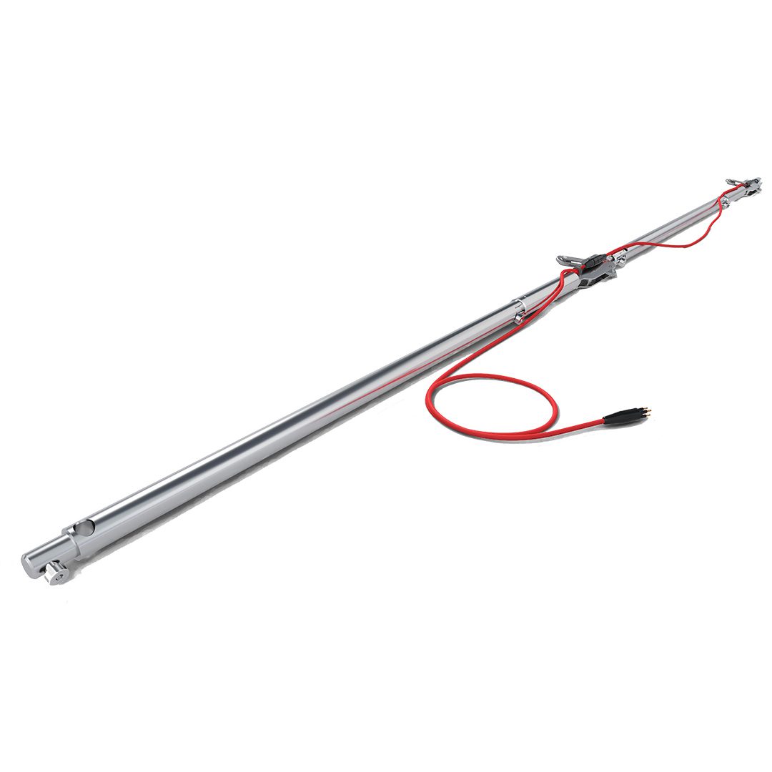
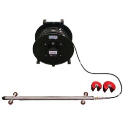
A typical inclinometer consists of 3 parts: i) a probe, ii) a readout device, and iii) a cable. A casing is also used to drive the probe into position and to protect the device from soil and water penetration.
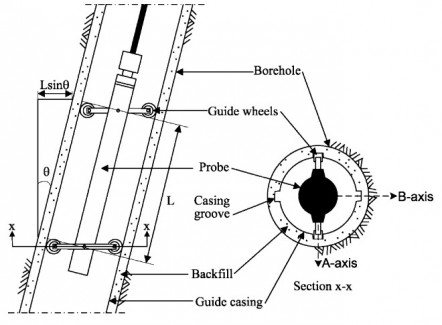
The probe is composed of at least one force-balanced accelerometer that measures the inclination of the casing with respect to the vertical direction. The commonly utilized inclinometers contain two accelerometers and use a biaxial probe.
Two wheels that enable the device to move within certain grooves in the casing are attached to the probe at a fixed relative distance (0.5 meters). One accelerometer is placed parallel while the other is placed perpendicular to the wheels. The accelerometers measure the tilt of the casing with respect to the vertical direction in both horizontal directions. The layout of a typical probe inclinometer along with the inserted wheels and the directions of measurements (A- and B- axes) is depicted in Figure 1.

The cable is attached to both the probe and the readout device and its role is twofold:
- It provides the device with electrical current during the measurements, and
- It serves as a depth measurement device. Therefore, it has measurement markings every 25 centimeters and it must be designed to be durable, waterproof and rigid.
The readout device records the inclinometer’s measurements and is capable of storing data. It is equipped with a rechargeable power supply.
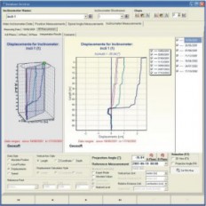
Data accumulation, editing and management are conducted via a computer software. The sensors may also collect data concerning precipitation rates, groundwater level or temperature that can be associated with the results of the test.
Inclinometer Installation
Vertical Slope Inclinometers
Vertical slope inclinometers are installed within boreholes which are shafts relatively small in diameter bored in the ground. The borehole should be large enough to accommodate the device’s casing and a pipe from which grout will be inserted.
Segments of the casing are placed in the borehole until the desired depth. The casing must be installed 3-6 meters deeper from the point where displacements are expected to be eliminated.
Two grooves are then installed carefully in order not to apply too much torque on the casing.
The guide grooves must be kept clean via water hosing or brushing during the installation so that tracking problems will not emerge.
Grout, a mixture of water, Portland cement and bentonite, is pumped through the pipe and into the borehole. The purpose of using grout is to bond the slope inclinometer with the surrounding soil.
Once the system is installed, the internal part of the casing must be kept clean so that the probe travels via the grooves without obstructions.
It should be noted that a vertical inclinometer is utilized to derive the horizontal deformation of the ground.
Horizontal Slope Inclinometers
The function of a horizontal slope inclinometer is similar to that of the vertical inclinometers. However, they are installed in horizontal boreholes in which either one or both ends attach to the surface of the ground.
The grooves must be aligned vertically without any twisting and their perpendicularity is verified during the addition of a new casing segment.
Horizontal slope inclinometers are used to derive the vertical movement of the ground.
Inclinometer Measurements
The inclinometer’s probe is inserted into the casing and its tilt is derived by taking consecutive measurements at every 50 centimeters (the distance between the two wheels inserted). On special occasions, more measurements can be taken in smaller intervals to provide more accurate results.
The reading process begins at the base of the casing. The probe remains inactive for around 10-15 minutes so that its sensors stabilize with the temperature of the ground.
When the test is completed and the probe reaches the surface of the ground, it is rotated by 180 degrees and re-inserted into the casing so that the procedure can be repeated.
The horizontal displacement of the probe is derived via the following equation: S = L * sin(θ)
Where θ is the angle of tilt and L is the measurement interval (usually 0.5 meters as mentioned above).
A schematic of an inclinometer’s configuration is depicted in Figure 3.
If the base of the inclinometer casing is considered stable, tilt data from the bottom are accumulated to create cumulative results. Otherwise, the top of the casing is considered the reference point.
The accuracy of a typical inclinometer is ±7.6 millimeters per 30 meters but this is highly dependent on the type of the inclinometer. There are systematic errors which affect the reliability of the measurements and include minor faults in the installation of the probe, and random errors that are associated with the function of the sensors.
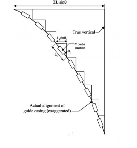
The ground’s deformation is derived via the cumulative alterations of the casing inclination and at a given depth as shown in Figure 4.
Evaluating the results of an inclinometer test requires engineering judgment to identify errors that could create deformation patterns that do not actually exist.
For example, in an active landslide, the movement is expected to occur within a distinct shear zone and therefore, the cumulative deformation over most of its depth must be minor.
Moreover, the general rule to identify shear deformation of a landslide is the determination of at least 2.5 millimeters movement within a shear zone. A smaller detected deformation may be a result of the aforementioned typical errors.
Experts recommend using the same probe and the same technicians to conduct multiple inclinometer tests during a project so that a certain level of consistency is maintained.
Critical Magnitude and Direction of Movement
Identifying the actual magnitude and direction of deformation is critical both in assessing structural performance and landslide movements.In the case of a vertical inclinometer, the horizontal ground displacements are derived using a biaxial probe. If the critical direction of movement is parallel to one of the A- or B- axes (Figure 1), the total deformation can be derived using the measured data of the corresponding axis.
However, this is not typically the case as the direction of movement is usually not aligned with one of those axes.
Therefore, the critical deformation (DC) and its direction are derived by adding the vectorial components of the measurements in the A- and B-axes (DA and DB, respectively), as presented in Figure 5.
References
Machan, G. and Bennett, V. (2008). Use of Inclinometers for Geotechnical Instrumentation on Transportation Projects: State of the Practice. Transportation research circular.
Equipment Providers
Looking for Inclinometer Equipment? Fill in the form and we will contact them for you.
Provider Companies
Orica Digital Solutions Geosolutions
VIEW
ShapeArray SAAV
The most advanced ShapeArray™ makes installation even simpler.

ShapeArray SAAX
Purpose-built with longer one metre segments for heavy duty horizontal installation.

ShapeArray SAAScan
Built for rapid deployment and repeated use.

ShapeArray SAAV Extend
Connect sensorized segments in the field for a continuous deformation profile.
MEMS Digital In-Place Inclinometer System
Designed to reliably measure lateral movement, particularly when continuous remote monitoring is required.
Digital MEMS Inclinometer System
For measuring any lateral movement down in the earth, via inclinometer casing.
Want to read more like this?
INCLI-pro
Oct, 14, 2013 | Software
Meet Measurand's SAA Centralizers
May, 27, 2015 | NewsTake a look at Measurand's SAA Centralizers! Centralizers are intended for use in installations wher...

GTILT
Oct, 14, 2013 | Software
Introduction to Slope Stability
Mar, 03, 2021 | EducationTopics on Slope Stability Analysis Geoengineer.org has gathered and presented educational mate...

Deep Supported Excavation in Urban Environment
May, 09, 2019 | Education"Measured vs. Predicted behavior", Degree thesis of Dimitris P. Zekkos, Civil Engineering Departmen...

SiteMaster
Jun, 15, 2023 | Software
Slope Stability: Example Analysis
Jul, 12, 2021 | EducationSlope Stability Analysis In this chapter of the Geoengineer.org series on Slope Stability, a s...
GTILT Plus
Oct, 14, 2013 | Software
Anatomy of a Reactivated Landslide: How Combined Analysis Informed a Difficult Decision
Feb, 04, 2026 | NewsA 21,000 m² landslide was actively threatening the settlement of Köprülü in northeastern Turkey. Gr...
Web Class Assignments
Looking for Inclinometer Equipment? Fill in the form and we will contact them for you.
GET A QUOTE NOWOn This Day
June 22nd 1969
READ MORE
Related Video

Trending

Point Load Test

Slope Stability: The Bishop Method of Slices
Angle of Internal Friction

Slope Stability: Introduction to the Method of Slices

Exploring the World’s 10 Tallest Dams

Splitting Tensile Strength Test (Brazilian)
7.5. Example Problems