Combining PLAXIS 2D and 3D Kept the Lueneburg Lock's Century Project Within 4 mm of Its Historic Neighbour Sponsored
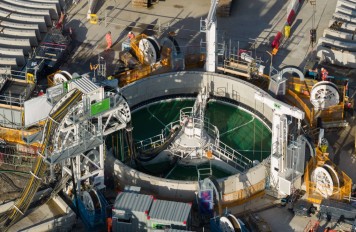
Engineers designing the new Lueneburg Lock in northern Germany used a deliberately complementary combination of PLAXIS 2D and PLAXIS 3D models, rather than a single large 3D model, to control a 30 m deep excavation next to the operating Scharnebeck twin ship lift, according to a paper presented at ICSMGE 2026.
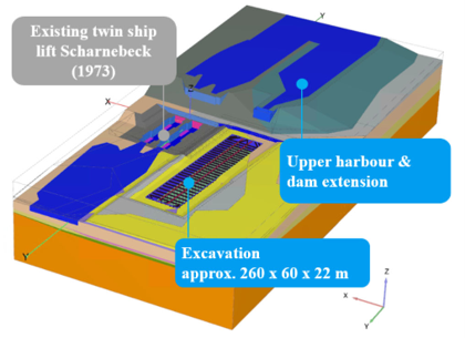
The paper, by Nataly Filipouskaya of Ramboll Deutschland GmbH, Prof. Dr.-Ing. Tim Pucker of HafenCity University Hamburg, and Lukas Brodersen of Wasserstrassen-Neubauamt Hannover, documents the numerical modelling strategy behind the Lueneburg Lock (Schleuse Lueneburg), a new lock on the Elbe Lateral Canal with 225 m long, 12.5 m wide basins and a 38 m water level difference, among the largest locks of its kind in Europe. The new lock will eventually replace the adjacent Scharnebeck twin counterweight ship lift, built in 1974 and the largest ship lift in the world at the time, which must remain operational throughout construction roughly 60 m away.
A Deliberate Argument Against an All-Encompassing 3D Model
The paper's stated aim is to challenge the assumption that 3D finite element models are automatically 'more accurate and better' than 2D models. The authors argue that attempting to build an all-encompassing 3D model can contradict the core numerical modelling principle of using symmetries and reducing complexity to the necessary level, and that the achievable level of detail in a 3D model is limited by hardware, software and meshing constraints. Because of the project's scale and the proximity of multiple structures, however, the project scope did specifically call for a large-scale 3D numerical model, built alongside a set of more detailed 2D models, using PLAXIS 2D and PLAXIS 3D (Bentley Systems, 2024) throughout.
Ground conditions, dominated by dense sands and gravels with basin silts and locally formed lenses of glacial till and tertiary clay, were first captured in a 3D ground model built in Leapfrog Works from 66 CPTs and 94 boreholes. This model fed soil layering into both the 2D cross-sections and the 3D FE model. Soil behaviour in PLAXIS was represented with the Hardening Soil small-strain (HSS) model, calibrated against the geotechnical interpretative report, triaxial and oedometer laboratory tests, and crosshole seismic data. The authors highlight that, because most soil units are overconsolidated (OCR of 6 to 8), careful calibration of the unloading/reloading Poisson's ratio, which governs the at-rest earth pressure coefficient for overconsolidated soil in PLAXIS's HSS formulation, was essential to a realistic simulation.
Getting a Complex Ground Model Into PLAXIS 3D
The paper describes practical difficulties in transferring the Leapfrog ground-model surfaces into PLAXIS 3D, noting that the exported surfaces typically carry a node density and curvature that exceed both the requirements and the capabilities of finite element analysis, while PLAXIS itself lacks adequate tools to simplify and adjust that geometry directly. The authors found that the most practical route was an intermediate step through Rhinoceros 8 software to reduce the mesh and convert it to a NURBS surface, or alternatively importing a point cloud directly into PLAXIS 3D, which automatically creates a NURBS surface but with a greater loss of precision. The paper also flags that PLAXIS's 14-digit coordinate precision can leave virtually identical nodes disconnected, producing non-watertight geometries and mesh generation problems, and recommends a parametric, coordinate-based geometry definition via the command line or Python interface as a practical workaround.
Where 2D and 3D PLAXIS Models Disagreed
Four cross-sections and one longitudinal section were modelled in PLAXIS 2D along the 255 m long excavation to assess horizontal bedding stiffness for the diaphragm wall (D-wall) embedment, earth pressure through each construction phase, D-wall deformation, internal forces, and lock settlements. Effective earth pressures derived from the 2D PLAXIS model, for example, were fed into the analytical design tool GGU-Retain following EAB (2021) recommendations, and the model showed that dewatering the pit reduced the earth pressure on the active side by around 35% relative to full excavation, a reduction the design team used to optimise the D-wall design.
The global 3D PLAXIS model, covering a 0.32 sq km (400 x 800 m) domain, was used to compare structural excavation design results directly against the 2D models at the critical southern D-wall, identified because of its proximity to the dam, its position at the deepest excavation level, and the highest design groundwater pressure. The comparison found the 3D model's maximum D-wall bending moment 13% lower than the 2D result (5,184 vs 5,978 kNm/m), its minimum bending moment 55% lower (-1,373 vs -3,057 kNm/m), and its wall deformation 43% lower (4.61 vs 8.21 cm), while longitudinal and transverse strut forces matched closely between the two approaches (within about 0.5-0.6%). The 3D model additionally produced a corner strut force of 16.42 MN that has no 2D counterpart at all, since 2D cross-sections cannot represent excavation corners.
The authors attribute the more conservative 2D results partly to three-dimensional load distribution and transverse spanning effects at the southern wall, which has a length-to-width aspect ratio of 2.7, and partly to the tendency of 2D cross-sections to overestimate the volume and surcharge load of the adjacent dam, whereas the 3D model represents the dam's actual geometry. Using the 3D model, the authors calculated that the dam contributes about 9% of the bending moment on the southern D-wall.
Keeping the Historic Ship Lift Within Tolerance
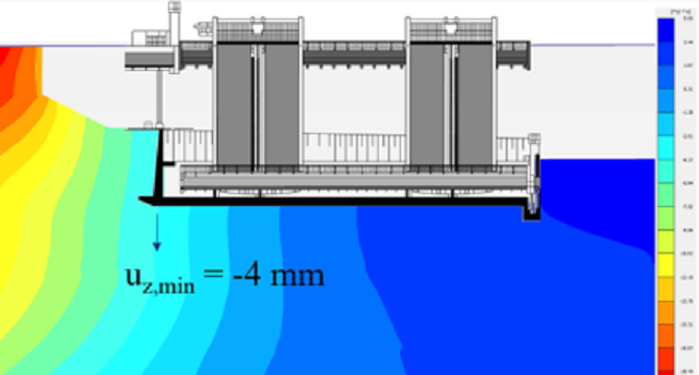
A central purpose of the global 3D PLAXIS model was to track the effect of each of the project's 13 construction stages on the existing Scharnebeck ship lift. The model showed that one side of the ship lift settles, primarily from the added mass of the new dam, while the opposite side heaves as a result of unloading during excavation and dewatering of the pit.
According to the paper, these PLAXIS-predicted vertical displacements at the ship lift foundation remained within a magnitude of 4 mm during the critical dewatered construction stage, which the authors describe as acceptable for a construction of this scale.
The authors conclude that the 3D FE models provided insight into complex interactions and three-dimensional load distribution despite their coarser discretisation, while the 2D FE models allowed a finer mesh and explicit representation of heterogeneous soil layers and lenses, supporting targeted parametric studies and rapid design iteration. They state that the complementary use of 3D and 2D PLAXIS models, rather than reliance on either alone, provided a resilient design methodology for the project's geotechnical challenges, and recommend that future work focus on refining modelling assumptions and corroborating the numerical predictions against field monitoring data.
Want to read more like this story?

Why Run PLAXIS 3D Analysis?
Jun, 07, 2021 | NewsMost geotechnical engineers use FEA software packages for their geotechnical design. It is especial...

PLAXIS 2023.2 New release is out!
Sep, 07, 2023 | NewsThis latest release solidifies Seequent's Connected Geotechnical Workflow, reducing the need for du...

How to create 3D dykes using SOIVISION 3D extrusion tools
Sep, 04, 2020 | NewsAdvanced 3D tools such as SVDESIGNER offer a lot of power to the user, but such power is not alw...

PLAXIS 3D – Traditional Tunnelling Method: Application Of MTM
Jun, 17, 2024 | NewsThis article aims, firstly, to enhance the current design approaches, via a new 2D approach based o...
3D PLAXIS Model Validates 2D Design for Geosynthetic-Encased Stone Columns Beneath Bavarian Roundabout
Aug, 07, 2026 | NewsA three-dimensional PLAXIS finite element model has been used to verify and cross-check a two-dimens...

New release of PLAXIS CONNECT Edition V20 Update 1
Jan, 20, 2020 | NewsPLAXIS CONNECT Edition version 20.0 includes streamlined user experience, increased performance an...

Bentley Webinar: FE and LE solution for Geotechnical Projects using PLAXIS WorkSuite
May, 11, 2022 | EventPLAXIS 2D/3D WorkSuite is the most comprehensive option of PLAXIS which includes PLAXIS 2D/3D Ultim...

Numerical Modelling: On the Importance of an Appropriate Soil Model
Jul, 22, 2021 | EducationThe following was prepared by Dr. Ronald B.J. Brinkgreve, and first presented by Virtuosity. Numeri...

PLAXIS CONNECT Edition V20 Update 4
Jan, 11, 2021 | NewsBentley Geotechnical Engineering experts are continuously improving PLAXIS CONNECT Edition. In this...
Form
Looking for more information? Fill in the form and we will contact Seequent, The Bentley Subsurface Company for you.
On This Day
August 12th 1848
READ MORE
Related Video

Trending
Brownfield success: Engineering excellence starts below ground

Scripting Comes to RS3: Automate, Customize, and Accelerate Your 3D Modelling

2D and 3D Analysis of Retaining Systems

Mine waste dam failure in Myanmar caught on video
Emergency ground stabilisation protects rail works near Salford Central