Subsea Tunneling Design and their reinforcement methods
Contents [show]
Introduction
Several advancements in tunneling have been made in the past century, especially in the area of submarine tunneling. As technology improves, such as computers and machinery, engineers have been able to design safer and stronger subsea tunnels measuring to be a couple of miles long. These tunnels serve an important role in transportation, sometimes serving as the main method of commuting for people indifferent areas in the world, so it is rather crucial that these tunnels are designed, analyzed and constructed properly to withstand any possible failure or collapse. This paper aims to better understand the different methods in protecting and reinforcing subsea tunnels from water intrusion or possible collapse and the technologies used by engineers and contractors to either install or excavate such tunnels.
Pregrouting
When excavating for a submarine tunnel, one important thing to always consider is seepage and water intrusions, as high quantities of water pressure are constantly acting upon the roof of the tunnel. Throughout various projects such as in China and the Channel Tunnel connecting France to England, grouting is used in order to line the tunnel’s interior or to seal fissures in imperfections in the tunnel walls. During the construction process of the Channel tunnel, crew members would pregrout the walls of the tunnel in order to lower the probability of any water intrusions from happening as a result of the TBM causing disturbances on the soil or rock. Another excellent example is the Seikan Tunnel in Japan. This tunnel was constructed during the 80’s and faced many geological conditions; as the geology of the sea bed consisted of fractured rock in multiple locations, engineers used grouting in order to prevent any water seepage. Engineers were able to find a relation between the radius of the tunnel face and the length of how far grouting should penetrate the rock. This relation is as such: “If the ground quality is good and seepage volume small, grouting is so made as to reach three times the tunnel radius. When the ground is weak or the seepage volume is extremely big, grouting reaches up to six times the radius.”[5] Although it was costly, this method proved worthy against the high water pressures the tunnel experiences, considering that the tunnel reaches a depth of 100 meters below the seabed. This tunnel continues to be in operation today and is the longest railroad tunnel in the world.

Fig 1. Number of subsea tunnels in Norway through late 20th century [9]
Of all countries implementing submarine tunneling into their infrastructure, Norway tends to dominate in the expertise. The country has around 33 subsea tunnels [13], and continues to increase that number yearly. By observation of the chart above [9], the Norwegian current trend is to build longer tunnels as time progresses. The chart also demonstrates that the body of water these tunnels are routed under are progressively more challenging to construct. With the majority of the country laying on either fjords or hard rock masses, the country has adapted to build underneath water instead of over. Norway also makes use of grouting in their tunnels, and takes geological considerations into mind as well. During the design process, multiple aspects are taken into consideration before moving any excavation even occurs. Of all these considerations, some top factors are the inclination angle of the tunnel axis, because it will affect the maximum length of the tunnel. An additional consideration is the cover between the tunnel’s ceiling and the bed of the body of water. Although a good amount of Norway’s geology consists of rock, it is still no easy task to construct tunnels without facing challenges during the excavation process. As demonstrated in the Atlantic ocean tunnel, a cave-in proved to be quite detrimental to the project and “More than 1000 tons of grout was needed to seal the leakages of the approximately 25 m wide fault/weakness zone.” [8]
Analysis Methods
Although Norway is leading in the subsea tunnel industry, other countries have taken their findings and used it in the heavy civil industry as well, adapting the scandanavian’s experience to their own country’s standard. The Chinese have integrated multiple countries’ findings and calculations for the design of their first subsea tunnel, spanning between Xiamen and Xiang'an.[11] For the rock cover needed, the engineers incorporated the “Japan least quantity of water inflow standard, Norway experience formula standard, and experience formula about determining reasonable coal and rock pillar of mining under water-bearing layers in China.”[14] Calculating using the Japan least quantity of water inflow standard, the equation below equated to a result of 12.41 meter rock clearance for the tunnel.

h = rock thickness (m)
H = water depth (m)
r = tunnel radius (m)
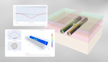
Many boreholes were used for this project, trying to determine what the geological conditions looked like at different depths throughout the sea between the island and mainland. After mapping of the seabed, engineers proceeded to run multiple analyses of different e geometries in order to optimize space and material necessary for reinforcement. After running multiple iterations through of finite element analysis, engineers were able to determine the best shape for the tunnel to reduce the amount of settlement that would occur in the tunnel lining and crown to 0.04 cm and 1.8 cm respectively. The figure below demonstrates how the final geometry of the tunnel was optimized and how much the values changed between the initial and final chosen configurations[7]. From the diagram we observe that the final geometry tends to spread moments around the shape more evenly compared to the initial condition. Additionally the final shape tends to have a lower overall normal force being applied to the crown of the tunnel. Lastly, the greatest improvement is demonstrated when plotting the factors of safeties at different locations of the geometry. There are drastic improvements in the bed of the tunnel from the optimized shape when compared to the original.

Liners
As submarine tunnels face the possibility of water intrusion at all times, multiple layers of protection are placed on the tunnel walls to lower the permeability of the tunnel’s walls. Most commonly used are concrete or shotcrete. These material layers allow the tunnel’s walls to act as a virtually impermeable wall, and are able to hinder the amount of moisture penetrating through the tunnel’s walls. By limiting the amount of moisture that is able to enter the tunnel, the levels of corrosion are significantly decreased, increasing the life of the tunnel. Controlling corrosion levels is especially important in excavations used for high speed railways. The design of the grade requires a lot of investigation. In order to prevent any corrosion inside the Channel Tunnel, engineers had to design the layers to be used for the bed of the tunnel. The goal was to maintain water below subgrade while being an easily drainable material, but maintain its stiffness throughout the tunnel. At the end of the design process, the bed was a combination of granular backfill, cements, and clays [10].
If casting concrete in place is not a viable option when lining the tunnel, an alternative is using precast concrete panels. Once again, the channel tunnel is a great example of this application. In certain areas of the tunnel’s excavation, the English and French used precast panels to line the interior of the tunnel [1]. These panels were composed of different thicknesses depending on the location and the rock properties. The overall liners inside the tunnel looked as such: “The permanent support normally consisted of a plain concrete lining cast inside the primary lining incorporating the provision of a waterproofing membrane. The secondary lining was designed to carry the full permanent loading and assumed no assistance from the primary lining.”[6]
As other countries look to develop new submarine tunnels, many design criteria are carefully taken into account. When Japan was designing the trans-Tokyo tunnel bay highway, one of the designs proposed was a shield tunnel. A shield tunnel allows for ease in constructability and permits for the mixed use of reinforcement options. Such combinations include the use of section joints and anchor bolts, which are a great combination for this specific project considering the area is a hot zone for seismic activity [4]. Combining shield tunneling reinforcement with liners lowers the possibility of a collapse and decreases the likelihood of water outbursts in the excavation as well.

Alternative Tunneling Methods
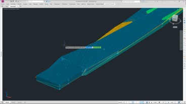
An alternative form of subsea tunneling includes the use of prefabricated tubes placed in a layer of submarine soil. During this process, trenches are most commonly excavated at the marine bed. Soon after the trench is excavated, the tubes are inserted and the trench is backfilled with the new tunnel underneath. This method of tunneling is most commonly seen where soil at the site is very soft or loose and easily prone to deformation [12]. The Bay Area Rapid Transit (BART) system has incorporated this technology in their transportation network, where bay mud and alluvium are the prominent geological conditions. This method proved worthy against the 1989 earthquake; it was resistant to any major damage and presented small amounts of water leakage, which were quickly repaired and allowed the BART to be fully operational the following day [3]. The figure depicts how the immersed tube is running through the soft material. As can be seen in the figure is that the two cities at which the tunnel goes through, Oakland and San Francisco, used two different methods. San Francisco opted for the shield tunnel method, whereas Oakland uses the cut and cover method.

TBM’s for Subsea Tunneling
The design of submarine tunnels faces many challenges requiring innovative and creative ways to address the challenges. However, there are multiple challenges faced by the construction team, ranging from budget to the method of excavation. Depending on the site conditions, desired tunnel depth, and material properties, the use of a TBM, blast method, or jumbo is considered for tunnel excavation. Current TBMs require routine maintenance and are usually meant to bore through one material. Modern day TBMs are also exposed to astonishing quantities of water pressure. With the advances occurring in the geotechnical field, especially in the field with devices and machines, there is research dedicated into the manufacturing of a TBM for the sole purpose of subsea tunnel boring [2]. These new machines would be able to withstand large water pressure and be able to bore through heterogeneous materials. Most importantly, these machines attempt to excavate larger distances and intend to extend the time between necessary repairs and maintenance operations.
Conclusion
Submarine tunneling is a specialty expertise, requiring hours of site condition investigation and analysis before proceeding with any design calculations. Countries across the globe,use ingenious methods to reinforce subsea tunnels that will cross through varying geological conditions. Be it deep sea tubes, or tunnel shields, or as simple as concrete linings, there are different measures set in place to protect the tunnel and extend its operation life. Seismic conditions also play a major role when engineer’s are trying to determine the reinforcement method to implement in their tunnel. Tunnels must be able to withstand major displacements caused by tremors while continuing to function such as the BART system in the bay area during the 1989 earthquake. As of now, deepsea tunneling is becoming a trend for crossing large bodies of water, but with time, alternative options are being considered, such as suspended tubes in water. How viable are options like these? Only time will tell.
Sources
[1] C.J. Kirkland, “The proposed design of the English Channel Tunnel”, Tunnelling and Underground Space Technology, Volume 1, Issues 3–4, 1986, Pages 271-282
[2] Duhme, Ruben, and Thorsten Tatzki. “Designing TBMs for Subsea Tunnels.” Journal of the Korean Tunneling and Underground Space Association, vol. 17, no. 6, Korean Tunneling and Underground Space Association, Nov. 2015, pp. 587–596
[3] Dunn, James, et al. "Raising the Bar on BART." Civil Engineering, vol. 71, no. 12, 2001, pp. 60-65.
[4] Keinosuke Uchida, Yujirou Wasa, Makoto Kanai, “Design of the shield tunnel for the trans-Tokyo bay highway”, Tunnelling and Underground Space Technology, Volume 7, Issue 3, 1992, Pages 251-261
[5] Kitamura, Akira, and Yuzo Takeuchi. "Seikan Tunnel." Journal of Construction Engineering and Management 109.1 (1983): 25-38.
[6] Lance, Guy, et al. “Section II: Tunnelling.” Engineering The Channel Tunnel, CRC PRESS, 1995, pp. 63–78.
[7] Li, Pf., Zhou, Xj. “Mechanical behavior and shape optimization of lining structure for subsea tunnel excavated in weathered slot.” China Ocean Eng 29, 875–890 (2015).
[8] Nilsen, Bjorn. "Main challenges for deep subsea tunnels based on norwegian experience." Journal of Korean Tunnelling and Underground Space Association 17.5 (2015): 563-573.
[9] Palmstrom, Arild. "Norwegian experience with subsea rock tunnels." Tunnels and Water (1989): 927-934.
[10] Phear, Alan, and Nick O'Riordan. "Earthworks for the channel tunnel rail link high speed railway, UK." Geotechnical Engineering for Transportation Projects. 2004. 1621-1628.
[11] Sze, James. “First Subsea Tunnel in Mainland China.” Arup
[12] Thomas R. Kuesel, “Alternative concepts for undersea tunnels”, Tunnelling and Underground Space Technology, Volume 1, Issues 3–4, 1986, Pages 283-287
[13] Wikipedia contributors. “List of Subsea Tunnels in Norway.” Wikipedia, 7 Oct. 2020.
[14] Zhang, Lewen, et al. "Preventing Water Outburst in Excavation in Subsea Tunnel." International Conference on Transportation Engineering 2009. 2009.
 Carlos Jimenez
Industry News


Enable true ground-informed design in Civil 3D

Events

19th European Conference on Soil Mechanics and Geotechnical Engineering, Istanbul, Türkiye
The 10th International Congress on Environmental Geotechnics

11th European Conference on Numerical Methods in Geotechnical Engineering

1st International Conference on Sustainability in Geotechnical Engineering (ICSGE 2027)

The 4th International Conference on Press-in Engineering 2027 (ICPE2027)

International Symposium on Cone Penetration Testing (CPT'27)

Rocscience International Conference 2027: Geotechnics, Structures & Hydro in the Age of AI
IS-GI Lyon 2027: International Symposium on Ground Improvement