Contents [show]
- Introduction
- The Physics
- The Chemistry
- The Applicable Soils and Types of Contaminants
- Types of Barriers and Their Construction
- Advantages
- Disadvantages
- ZVI Pilot Scale Case Study, Colorado
- ZVI Pilot Scale Case Study, Montana
- ZVI Full Scale Case Study, Massachusetts
- GAC Computer Modeling Case Study, Italy
- GAC Laboratory and Modeling Case Study
- Limestone Full Scale Case Study
- ORC Column, Batch and Bench Scale Modeling Case Study
- Recommended Reading
- References
Introduction
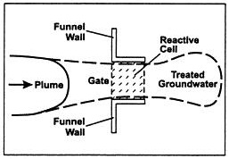
The definition of a Permeable Reactive Barrier (PRB) by the EPA is:
“An emplacement of reactive media in the subsurface designed to intercept a contaminant plume, provide a flow path through the reactive media, and transform the contaminant(s) into environmentally acceptable forms to attain remediation concentration goals down-gradient of the barrier.” (Thiruvenkatachari, Vigneswaran, & Naidu, 2008)

Figure 1: Basic layout design of a PRB within a contamination plume. (University of Newcastle Australia, 2012)
The PRB was first implemented in 1991 as an alternative to the conventional pump and treat method. (Olson & Higgens, 2009) The layout design of the permeable reactive barriers can vary depending on the contaminant plume that requires remediation techniques. There are multiple variations of permeable reactive barriers; the two types covered in this project are: trench/continuous wall and funnel and gate. According to US EPA survey in 2002, 30% of PRBs use continuous trench and 30% use funnel and gate, with the rest being less common methods. (Olson & Higgens, 2009)
The reactive media used in the PRB will vary depending on the reactive qualities of the contamination plume. The most common reactive medium is Zero Valence Iron (ZVI), representing approximately 55% of the PRB installations in 2002. (Olson & Higgens, 2009) This project covers the usage of ZVI, as well as Granular Activated Carbon (GAC), Limestone and Oxygen-Releasing Compounds (ORC) and their use as reported in various case studies.
The Physics
The Permeable Reactive Barrier (PRB) relies on a passive technique, meaning it requires no external energy to force the contaminated liquid through the barrier. To allow the water to flow through the reactive material, the reactive barrier material must have a higher hydraulic conductivity than the surrounding contaminated soil. (Di Natale et al., 2008) The PRB is then placed perpendicular to the direction of the water flow allowing the contaminated water to travel through the reactive material for the best removal results. Within the barrier the contaminants are either absorbed, chemically or biologically degraded. (Yeh, Lin, & Wu, 2010) Once the chemical process is complete, the remediated water continues downstream via natural flow.
 |  |
| a) Continuous wall plan view | b) Funnel and gate plan view |
Figure 2: The plan view of a contaminant plume intersecting a PRB (Gavaskar, 1999)
The Chemistry
The Permeable Reactive Barrier’s reactive material varies depending on the constituent(s) that need removal. The most common reactive materials used in PBRs are Zero-Valent Iron (ZVI) and Granular Activated Carbon (GAC). There are other types that are used less frequently than ZVI or GAC, however the effectiveness of these materials has not been studied as well as ZVI or GAC. Examples of these reactive materials can be found in Table 1.

Table 1: Reactive materials used in Permeable Reactive Barriers. (Bronstein, 2005)
There are four types of reactive processes used in a PRB to remove contaminants from the groundwater: (Bronstein, 2005)
- Abiotic reduction
- Biotic reduction-oxidation
- Chemical precipitation
- Sorption or ion exchange
In abiotic reduction, Zero-Valent Iron is the primary reactive material used (Bronstein, 2005) because it reduces the ionic state of passing contaminants, so the contaminants degrade to less harmful compounds that either precipitate out or flow through the barrier. (Thiruvenkatachari et al., 2008) Examples of reduction of uranium and chromium are shown in Figure 3a, below. Another common abiotic reduction by ZVI is chlorinated organic solvents. (Vogan, 1999) This process is shown in Figure 3b, below, where the chlorinated organic compound such as PCE or TCE is represented by R-Cl.

Figure 3a: Example of abiotic reduction chemical processes (Bronstein, 2005)
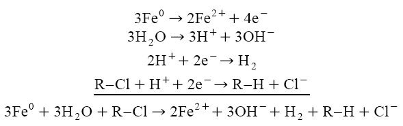
Figure 3b: Abiotic reduction of a chlorinated organic compound (Vogan, 1999)
Biotic reduction/oxidation uses reactive materials that promote microbial growth to degrade contaminants. Some materials include Oxygen Releasing Compounds (ORC), which provide the dissolved oxygen and nutrients necessary to grow microorganisms which can then break down the contaminant. (Yeh et al., 2010) Sulfate reducing bacteria is another example of this technique, which degrades the contaminant so the metals bind with sulfur and precipitate out of the contaminated water. (Bronstein, 2005) The chemical process is shown in Figure 4.

Figure 4: Example of biotic reduction/oxidation chemical process with sulfate reducing bacteria (Bronstein, 2005)
Chemical precipitation utilizes materials that react with constituents to form a solid state, which precipitates out of solution allowing for easier removal. The most common material for this technique is limestone. (Bronstein, 2005) Figure 5 gives an example of mineral precipitation using a hydroxide such as apatite and a carbonate such as limestone.

Figure 5: Example of chemical precipitation chemical processes (Bronstein, 2005)
In sorption or ion exchange the reactive material promotes adsorption of the contaminant to the material for removal from groundwater. The absorption process occurs when the molecules or particles bind to a solid surface. The common materials used in this technique are ZVI, zeolites, amprphous ferric oxyhydroxide (AFO), and activated carbon. (Bronstein, 2005) Adsorption treatment techniques can be used in activated carbon PRBs for a PCE polluted site as an alternative to abiotic reduction. (Di Nardo et al., 2010)
The Applicable Soils and Types of Contaminants
Applicable Soils
When considering if a Permeable Reactive Barrier will be adequate to reduce the contaminants in the ground, the surrounding soil properties need to be analyzed. The PRB must be designed to be more permeable than the surrounding aquifer soils, so identifying the permeability of the soil is important. (Thiruvenkatachari et al., 2008) For example, the commercially available granular activated carbon (GAC) (Aquacarb 207EATM) has a hydraulic conductivity of approximately 0.001m/s. (Di Nardo et al., 2010) When the reactive material has a higher hydraulic conductivity than the surrounding soils the contaminated groundwater moves under a natural hydraulic gradient through the reactive material. (Di Nardo et al., 2010) Once the permeability of the soils is considered, a PRB can ideally be placed in any soil because the mechanical properties of the soil primarily affect the flow of the water. However, the soil chemical and physical properties will affect the construction of the barrier discussed in the Construction section of this report. The geochemical properties of the soil will also determine the type of reactive media to be used in the PRB. For example, groundwater contaminated with PCE may not be best with a ZVI PRB. The ZVI causes a series of reduction reactions which can lead to precipitation and result in reduced hydraulic conductivity of the PRB (Di Nardo et al., 2010). Adsorption by an activated carbon PRB, alternatively, can immobilize the PCE in the barrier to circumvent contaminant precipitation and the corresponding issues such as clogging. (Di Nardo et al., 2010) Certain interactions between contaminants and reactive media can induce unintentional precipitation due to increased pH. (Thiruvenkatachari et al., 2008)
Types of Contaminants
Analyst estimate that there are between 300,000 and 400,000 sites in the USA contaminated with a wide variety of toxic chemicals representing cleanup cost in the range of 500 billion to 100 trillion dollars. (Thiruvenkatachari et al., 2008) “Many of these sites experience groundwater contamination of complex mixtures of chlorinated solvents, fuels, metals, or radioactive materials.” (Thiruvenkatachari et al., 2008)
Groundwater contaminants originates from two categories of sources, point sources and distributed non-point sources.
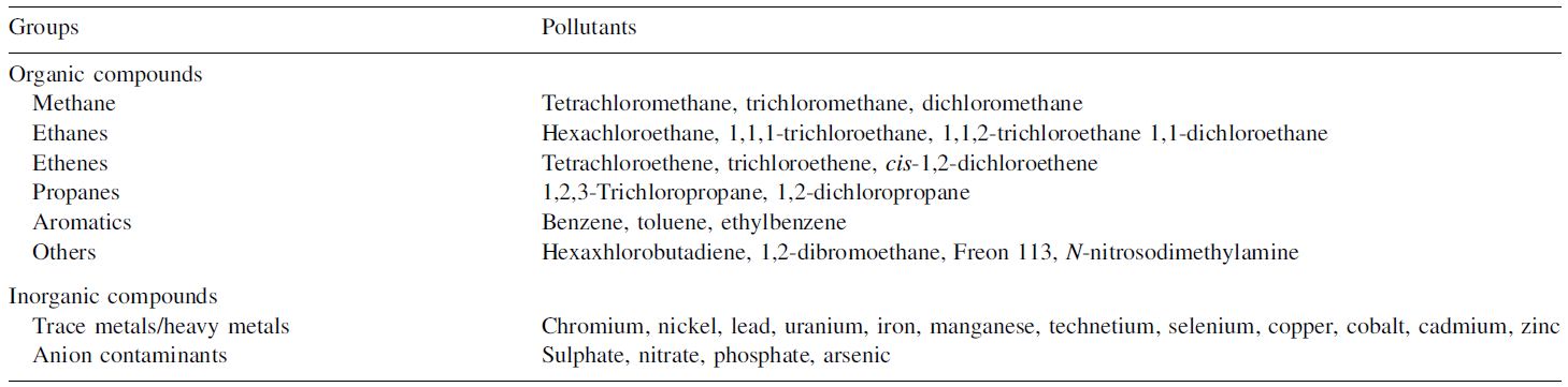
Figure 6: Examples of common contaminants found in contaminated groundwater (Thiruvenkatachari et al., 2008)
The two classifications of the contaminants are organic and inorganic. Organic contaminants can be broken down into elements and compounds that are then remediated from the plume. (Thiruvenkatachari et al., 2008) Conversely, most inorganic contaminants themselves are elements and cannot be broken down but can only change speciation. Therefore remediation strategies in removing inorganics include precipitation, adsorption and transformation into non-toxic forms. (Thiruvenkatachari et al., 2008).
Types of Barriers and Their Construction
Site Characteristics
Certain site characteristics such as hydrogeology, geochemical, hydrochemical, contaminant distribution, and microbiology must be evaluated prior to installation. (Bronstein, 2005) Hydrogeology, geochemical and contaminant distribution affect the location, configuration and reactive media of the PRB. Microbes present in the site can enhance the effectiveness of PRB. (Yeh et al., 2010) The depth, hydraulic conductivity, porosity, dispersivity, etc. characteristics of an aquifer must be well established to determine the PRB placement because the barrier efficiency differs with varying working conditions. (Di Natale et al., 2008) Factors surrounding the site, including: weather, surrounding surface water bodies, and surface conditions, must also be assessed because these variables will alter the water flux and can potentially increase the contaminant concentration. (Di Natale et al., 2008)
The contaminant type undergoing remediation and its distribution pattern must be considered to determine the appropriate medium and PRB characteristics, such as width and configuration. The geochemistry of the contamination site can affect the reactivity of the PRB material and change the lifespan of the barrier. (Bronstein, 2005) Therefore a geochemical study needs to take into account the pH levels, redox potential, dissolved oxygen, and minerals present for the specific site. (Bronstein, 2005)
Design
Configuration
The two most conventional setups for a PRB are continuous wall and funnel-and-gate. (Thiruvenkatachari et al., 2008) (Day, O’Hannesin, & Marsden, 1999) The continuous wall configuration is the most common configuration as of 2005. (ITRC, 2005) Both configurations are proven to be effective, but one might be more preferable than the other depending on the contaminated site.
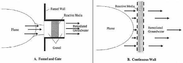
Figure 7: Typical configurations of a Permeable Reactive Barrier (ITRC Mining Waste Team, 2005)
A continuous wall configuration places a PRB in a trench perpendicular to groundwater flow. It is the simplest to install and typically covers the entire width and depth of the contamination plume. (Day et al., 1999) The characteristics of the site (water flow and the type of contaminant) will determine the width of the PRB to ensure proper reaction time and velocity. The continuous configuration is recommended to be anchored to an impermeable layer to reduce the potential of groundwater underflow. (Bronstein, 2005)
Funnel and gate systems consist of impermeable sides, such as sheet piling or slurry walls that divert contaminated groundwater into a reactive gate. (Bronstein, 2005) This ensures that the entire groundwater in the site goes through the reactive material to remove the contamination. (Day et al., 1999) Typically, the ratio of the length of the funnel to the length of the gate is less than six. (Day et al., 1999) The groundwater velocity through this gate is several times higher than the natural velocity. (ITRC, 2005)
In comparing the continuous wall to the funnel and gate system, a continuous wall configuration is sometimes chosen because it minimizes the potential for bypass around. (Vogan, 1999) A funnel and gate configuration is preferred when the reactive material is expensive because the funnel and gate utilizes less reactive media than the continuous wall. (Thiruvenkatachari et al., 2008) The construction cost of a continuous type barrier is significantly cheaper than the funnel and gate system. (Thiruvenkatachari et al., 2008)
The width of the PRB should be wide enough for the residence time of the contaminated flow to be long enough for the chemical process to take place. In reduction processes, the design width is a function of groundwater velocity and the residence time needed to reduce the contaminant concentration. (Richards, 2008) When designing the width (W) for an adsorption process, it should satisfy the inequality:
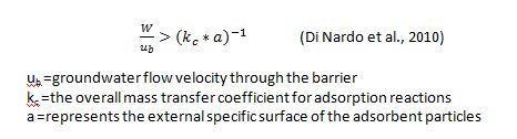
The flow of the contaminants is not always continuous, so a period of desorption may take place within the barrier causing contaminants to be released downstream. (Di Nardo et al., 2010) Designing a wider barrier can allow this process to be slowed preventing any contaminant concentration peaks from occurring and improving the overall long-term performance. (Di Nardo et al., 2010)
Types of Reactive Material (Physical Properties)
ZVI
ZVI is an oxidized compound that passes electrons to contaminants when they come in contact with one another. ZVI treats contaminants such as organic-halogenated hydrocarbons, inorganics, and metals. The reaction tends to degrade or precipitate out contaminants when reduced by the ZVI. (Thiruvenkatachari et al., 2008)
GAC
Activated carbon is a chemically stable material with a high adsorption capacity for organic compounds because of its large surface area. The effectiveness of GAC on inorganic compounds has yet to be evaluated. There is a possibility of repeated use of this reactive material through phosphate extraction, acid washing, and recently, microbial regeneration. (Thiruvenkatachari et al., 2008)
Limestone
Limestone is used in the remediation of anionic and cationic compounds. It is also effective in reducing the solubility of certain metals. This material is inexpensive. (Thiruvenkatachari et al., 2008)
ORC
Dissolved oxygen content is very low in groundwater. Oxygen releasing material can create an aerobic environment and allow for microbiological growth. This growth enhances the PRB and assists in degrading the contaminant. (Yeh et al., 2010)
Contruction
The Permeable Reactive Barriers can be constructed using conventional excavation techniques, a slurry mixture to prevent collapse, or by hydrofracturing to place the reactive material. (Day et al., 1999) The type of construction method depends on the type of configuration being used in the design of the PRB as well as the depth of the contamination. It is also “good practice to key the PRB into an underlying low-permeability layer to ensure complete capture and as a safeguard in the event the permeability of the PRB is reduced.” (ITRC, 2005) However it is not necessary to key into a low-permeability layer because it is not the goal of the PRB to prevent flow. (ITRC, 2005)
One of the more common methods of constructing a PRB is to use a biodegradable slurry that allows the trench or excavation to remain open during construction (ITRC, 2005). This method is preferred over using sheet piling due to cost comparisons. (ITRC, 2005) However when creating shallow trenches, hydraulic shoring or trench boxes can still be used for temporary support (ITRC, 2005).
The most common polymer used in a biodegradable slurry is guar gum because this solution is more easily degraded than a bentonite solution. (Day et al., 1999) The reactive material is placed in the trench while the biodegradable slurry remains in place. (Day et al., 1999) Recirculation wells are then placed surrounding the trench to break down the slurry mixture with enzymatic breaker fluid. (ITRC, 2005) It is important that the slurry material is degraded because, while in place, it affects the permeability through the reactive medium. A trench can reach a depth of 27m (90 feet) and a thickness of 0.6m (2 feet) using this method of excavation. (ITRC, 2005) However the stability of these trench/slurry walls relies on shear strengths of the soil and other soil characteristics which can vary significantly within a site. (ITRC, 2005)
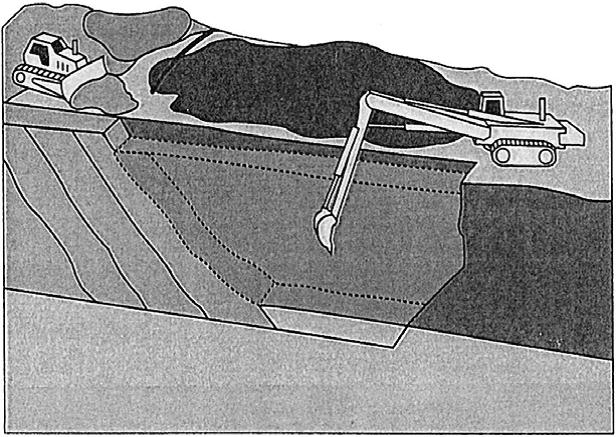
Figure 8: Construction of a slurry reinforced PRB trench (Day et al., 1999)
Another method of construction is using vertical hydrofracturing which allows the PRBs to be placed deeper than excavation or slurry supported trenches. (ITRC, 2005) For example, a continuous wall’s reactive material can be placed deeper than 90m (300 feet) and up to 0.2m (9 inches) thick with hydraulic fracturing. (ITRC, 2005) This method would be ideal in urban areas for deep contamination because this method does not disrupt the surface as much as trenching. (ITRC, 2005)

Figure 9: Construction of a PRB using the hydrofracturing technique (Tinker Air Force Base, 2006)
The trench construction is just as important as the site characteristics and determining the type of reactive material. This report covers a case study where the construction process led to a failure in the PRB causing some contamination to be transported downstream in higher concentrations than preferred. See the ZVI Case Study, (Richards, 2008), for more details.
Advantages
Advantages (of all the types)
The PRB is thought to be more cost effective at treating shallow aquifers in comparison to conventional pump and treat technologies; however long term cost data has not been collected for a full scale PRB. (Bronstein, 2005) These cost reductions are because the PRB should not require operation or maintenance of the reactive material. (ITRC Mining Waste Team, 2005) Pump and treat techniques have a higher energy demand than the PRB because the PRB can use natural hydraulic gradients to drive the remediation. (Bronstein, 2005)This little to no energy requirement by the PRB system means there is no necessary construction of above-ground facilities, which can be an advantage in an area that cannot be built upon. (Yeh et al., 2010)
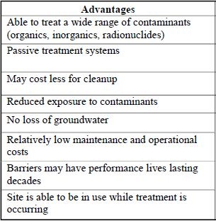
Table 2: Advantages of using a PRB (Bronstein, 2005)
Reactive Material Advantages
Zero Valent Iron
This material is the most commonly used reactive material in the PRB; there is more data on how this material will behave with a given contaminant than the other types of reactive materials. ZVI is also highly reactive with organic and inorganic contaminants. (Thiruvenkatachari et al., 2008) This is important when trying to remediate a wide variety of contaminants that may be present at a site. The ZVI has different sizes and chemical states so it can easily adapt to different load of contamination and the water flux required. ZVI can be used in combination with other methods of remediation such as bioremediation for more effective remediation for certain types of contaminants. (Thiruvenkatachari et al., 2008) ZVI is also safe for the workers constructing the PRB because there are no major occupational health hazards when handling the material. (Thiruvenkatachari et al., 2008)
Granular Activated Carbon
This material is relatively inexpensive because it can be obtained from low cost natural products. (Thiruvenkatachari et al., 2008) It is best used when a site has organic or heavy metal contaminants as it is most effective when in contact with these chemicals. (Thiruvenkatachari et al., 2008) GAC is also chemically stable allowing for accurate applicability. (Thiruvenkatachari et al., 2008)
Limestone
Lime is also relatively cheap to produce and can be used in combination with other treatment processes. (Thiruvenkatachari et al., 2008) Lime is useful with reducing the solubility of certain metals allowing the barrier to pull these metals out of solution in a form of precipitate. (Thiruvenkatachari et al., 2008)
Disadvantages
Disadvantages (of all the types)
The main disadvantage of the Permeable Reactive Barrier is that there is limited information about long term performance of the PRB in-situ. (Olson & Higgens, 2009) Since PRBs have only been created in the field since 1991, there are limited amounts of full-scale case studies. Also many of these case studies have been determined to be impacted by the method of construction. Another secondary disadvantage for the PRB is the sensitivity to the accuracy of construction, which can be difficult to determine at depth. For example, if a boulder is encountered and not removed the flow of the contamination can evade the PRB. (Richards, 2008)
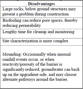
Table 3: Disadvantages of using a PRB (Bronstein, 2005)
As mentioned previously in the Design section, the width of the barrier is a function of basic hydrology (groundwater velocity and hydraulic conductivity) and residence time between the reactive media and the contaminant(s). Limited understanding of the complete flow regime such as directional changes with changing seasons can reduce the effectiveness of the PRB. (ITRC, 2005) Changes in geochemistry from reactions such as mineral precipitation or pH changes can significantly reduce the hydraulic conductivity and result in PRB failure. (Wilkin et al., 2009)
Reactive Material Disadvantages
Zero Valent Iron
The lifetime of this material can be reduced due to the contamination coating the surface of the ZVI particles, preventing flow through the barrier due to this build-up. (Thiruvenkatachari et al., 2008) The iron reactivity could also be reduced if it comes into contact with silica or natural organic matter. (Thiruvenkatachari et al., 2008) Also the ZVI increases the environmental impact of the PRB due to the creation of the material itself being an energy intensive process. (Olson & Higgens, 2009)
Granular Activated Carbon
Due to GAC being used less in PRBs than ZVI, there is limited data on in-situ treatment under field conditions. Also the performance of the GAC is highly dependent on temperature and other extrinsic parameters. (Thiruvenkatachari et al., 2008) As with the ZVI, surface coating may decrease adsorption capacity of the GAC. This decreased capacity will caused the GAC to be less efficient in removing the contamination from the groundwater if the design does not account for the change in adsorption capacity.
Limestone
Limestone barriers need to account for lime’s slow reaction time when coming into contact with the contaminants. (Thiruvenkatachari et al., 2008) Contaminants coating the lime particles with iron precipitates also caused a loss in efficiency of the barrier. (Thiruvenkatachari et al., 2008) Lime is affected by extrinsic parameters such as pH levels. Lime is not effective in acidities higher than 50mg/L. (Thiruvenkatachari et al., 2008)
Long-Term Performance
The long-term performance of PRBs is highly dependent on the site characteristics he long-term performance of PRBs is highly dependent on the site characteristics, flow patterns, and interactions between the contaminant plume and reactive media. Lifetime can be reduced due to unintentional precipitation of constituents either in the water or as contaminants, biofouling, and reduced reactivity of the PRB. (Bronstein, 2005) The ITRC looked at previous PRB applications and noted, "These lessons include reduced permeability due to construction, variability in the reactive media, aquifer heterogeneity, and the permeability contrasts affecting the groundwater flow." (ITRC, 2005)
ZVI Pilot Scale Case Study, Colorado
The following is a summary of The U.S. EPA’s findings of the pilot scale case study: (U.S. Department of Energy, 2005)
Background and Site Description
Cotter Corporation, located in Colorado, was a former uranium-ore milling site. The groundwater on this site was contaminated with both molybdenum (Mb) and uranium (U) with average concentrations of 4.8 mg/L of Mb and 1 mg/L of U. On site, groundwater flows through an alluvium containing unconsolidated sand, gravel, and silt. The bedrock is a mixture of clay, sandstone, and coal. The saturated thickness varies seasonally from 0.5 to over 4 feet from the ground surface. The site is estimated to have 1 gpm of groundwater flow.
PRB Design
In June 2000, a pilot scale funnel and gate PRB was installed using ZVI as the reactive material. The dimensions of the PRB were 30 ft long and 7 ft deep. In the direction of water flow, there was 2 ft of clean silica placed on either side of 5 feet of ZVI. Leading to a total width of 9 feet. The PRB was secured on either side with a vertical concrete wall. The funnel walls were 285 feet to the west and 85 feet to the east protected by a 36-mil layer of HypalonTM (a chemical, heat, and UV resistant synthetic rubber). Both the funnel and PRB were anchored 3 feet into the bedrock at the base.
The construction process began with the removal of soil from the ground surface using open excavation technique to a depth of three feet into the bedrock. Next, the concrete side walls and Hypalon wing walls were constructed. The last steps were filling the ZVI and sand and then replacing the overburden soils. The groundwater was pumped away during the entire construction process.
Results
The figures below show the dissolved Mo and U concentrations at different points along the funnel and gate system, from November 2000 to October 2004.
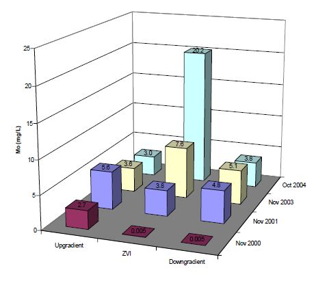
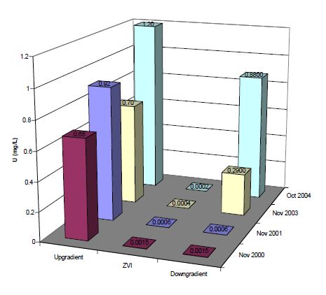
Figure 5 and Figure 6 from the report
An excavation was done to assess the PRB because of the high down gradient values for both the Mo and U concentrations. The visual excavation showed a cementation of ZVI almost entirely throughout the 5 foot span. Further testing showed that U, Mo, and Ca were the minerals present on the ZVI. Solid uranium was present only from 0 to 0.5 feet from the front of the ZVI at concentrations as high as 3.7 mg/g. Solid Mo reached its highest concentration from 0 to 0.5 feet from the front of the ZVI, ranging from 0.13 to 4.05 mg/g. Unlike uranium, Mo was found at slightly elevated concentrations up to two feet from the front of the ZVI. Calcium was present in high concentrations (up to 44.2 mg/g) from zero to 4 feet from the front of the ZVI. The author considers Calcium as the likely cause of cementation and loss of hydraulic conductivity of the ZVI.
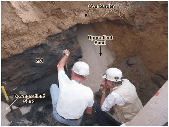
A photo demonstrating the cementation of the ZVI from the report
Discussion and Conclusions
The mineral deposits that caused the cementation of ZVI greatly reduced the hydraulic conductivity. “By early 2004, chemical signatures indicate that most of the ground water was bypassing the ZVI or was flowing through preferential pathways and not being treated.” (U.S. Department of Energy, 2005) Possible recommendations to prevent these issues include easy PRB accessibility, acid flush to remove calcium deposits, and the installation of a pretreatment zone with gravel and ZVI (Bronstein, 2005). These suggestions may serve to extend the life of the PRB by prolonging or eliminating mineral deposits, which increase the hydraulic conductivity allowing the contaminated water to flow through the PRB.
ZVI Pilot Scale Case Study, Montana
The following is a summary of Richard Wilkin’s findings of the pilot scale case study: (Wilkin et al., 2009)
Background and Site Description
This case study followed a pilot scale PRB design in East Helena Montana. This site was the location of a lead smelter that operated for over 100 years from around 1888 to 2001. The ground water under the site was contaminated with arsenic, selenium, lead, cadmium and zinc. There were also reports of plumes of arsenic and selenium that have travelled offsite. The contaminated groundwater traveled through unconsolidated alluvial deposits containing cobbles, gravel, sand and silt. Fine-grained volcanic ash tuff deposits lie beneath this alluvial deposit. The saturated thickness of the alluvial deposits ranged from 4.9-5.8m.

Figure demonstrating the contaminant plume and the recommendation of the PRB location taken from the report (EPA, 2006)
PRB Design
The pilot study used a granular iron reactive medium PRB with a length of 9.1m, a depth of 13.7m deep and a width of 1.8-2.4m. It was installed over a three day period using bio-polymer slurry methods and modified excavating equipment for deep trenching. The trench was backfilled with the granular iron from 13.7m-6.1m, with the remaining height being filled with sand. In order to make sure that the slurry didn’t affect the permeability of the wall, it was necessary to degrade the slurry with a flushing process. This process took approximately three days.
A figure demonstrating the trench construction and excavation taken from the report (EPA, 2006)
The top of the granular iron was >2m above the maximum groundwater level observed. However the bottom of the granular iron was approximately 1m above a layer of ash tuff, meaning the PRB was a “hanging wall” design. This hanging wall was destroyed to examine the effects of bypass processes.
The EPA estimated the construction cost at $325,000. (EPA, 2006)
Results
A monitoring network of wells were placed upgradient of the PRB, within the PRB, and down gradient of the PRB. Ground water samples were collected at 12 months, 15 months and 25 months downgradient. “After over 2 years of monitoring a pilot-scale, zerovalent iron PRB, results indicated arsenic concentrations >25 mgL-1 in wells located hydraulically upgradient of the PRB. Within the PRB, arsenic concentrations were reduced to 2 to -1.” (Wilkin et al., 2009) This showed that in the region with the PRB there was ~99% removal of arsenic from the groundwater. There were also no observed changes in the hydraulic conductivity of the PRB that would indicate corrosion and a precipitation build-up.
The results of the arsenic concentrations versus the side view of the PRB are shown in the following figure.

A demonstration of the flow of contaminants through the PRB
The spike in arsenic in the region where the PRB was not anchored into the ash showed that the groundwater was flowing beneath the PRB. This problem can be fixed with proper analysis of the subsurface and anchoring the PRB into an impermeable boundary forcing the arsenic to go through the PRB.
Discussion and Conclusions
The case study concluded that ZVI is effective in treating arsenic contaminated groundwater as long as the geochemical and hydrological conditions were properly analyzed. The study also mentioned that even though ZVI is accurate in removing arsenic from solution, it has a finite capacity. The flux evaluations in this study showed that the ZVI is highly effective if the amount of arsenic loadings are below 5 g As m-2d-1. Therefore analysis of the amount of arsenic flowing with depth needs to be accounted for in the design requirements of the PRB.
ZVI Full Scale Case Study, Massachusetts
The following is a summary of Peter Richard’s findings of the full scale case study: (Richards, 2008)
Background and Site Description
A full scale case study took place at a contaminated site in Needham, Massachusetts. This site had a plume of chlorinated solvents resulting from an electronics manufacturer that was migrating toward two public water-supply wells. The primary chlorinated solvent was trichloroethene (TCE) had as high as 1,100 μg/L concentrations. The goal of the PRB was to reduce the contaminates to 5 μg/L (the maximum contaminant level) or less.
The PRB was installed in 2001, and data was collected from October 2001 to 2007.
PRB Design
The PRB was designed in two sections due to the variability in the TCE concentrations across the site. Zone A was designed to be placed at the location with the highest concentrations in the plume (from surface to depth of 38 feet) while Zone B was designed to be keyed-in to the bedrock surface (from surface to depth of 55 feet). Due to Zone A having higher concentrations of contaminants it had a width of approximately 1.7 feet of iron whereas Zone B had a width of 0.5 feet of pure iron.
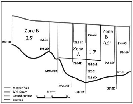
A cross section of the PRB showing the two types of zones taken from the report
Results
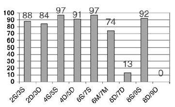 A figure demonstrating the reduction of the TCE in percentage in comparison between two wells.
The data results showed that the PRB is effective in removing, on average 80 percent of the TCE from the groundwater. In comparing upgradient and downgradient well data the PRB reduced the TCE concentration to 5 μg/L, the goal value of the contamination.
There were however, two locations where at depth the concentration of TCE downgradient showed little to no improvement when compared to upgradient. These high concentrations indicated either a design or construction issue with the PRB. These flaws can possibly be described by: higher permeability values than predicted, higher TCE concentrations in an area that doesn’t have adequate ZVI width, a construction related issue, or improper anchoring to the bedrock. The author analyzed each of these possible contributing factors to determine that a construction related issue was the most likely contributing factor. Analysis of the different parameters can be found in more detail in the paper.
The two primary sources of error that the author contributed to these high concentration values were cobbles being present or a flaw in the trench excavation. A boulder was encountered but not removed by the bedrock which could possibly lead to flow that does not come into contact with the ZVI. However, the author also notes that there was a slurry “failure” during which the slurry had to be enhanced with higher viscosity fluid and elevated pH levels. Boreholes were taken after the ZVI was put in place to determine if the width and mixing of the ZVI was accurate with depth. There were no direct indications of a trench failure, but a micro failure could have occurred leading the author to conclude that a construction-related issue was the most possible reason for higher TCE levels at the bedrock downgradient.
Discussion and Conclusions
The author concluded that the ZVI remediated most of the TCE concentrations in the plume, with the exception of the two areas discussed in the previous section. The author notes that the PRB would have had higher TCE contamination removal if the PRB was properly constructed as designed.
GAC Computer Modeling Case Study, Italy
The following is a summary of Armando Di Nardo’s findings of a model PRB case study: (Di Nardo et al., 2010)
Background and Site Description
This case study uses a contaminated site in Campania Italy as a background example for a model design of a PRB. This site had a source of eight million tons of urban and special wastes (legal and illegal). The aquifer is located at a depth of 35-40m beneath the ground surface. The groundwater aquifer was contaminated with inorganic and organic pollutants. For example, the PCE concentrations are approximately 20 times higher than Italian regulatory limits (1.1 μg/l).
PRB Design
The author used computational fluid dynamics software to model the water flow through and around the barrier. The barrier considered would be a continuous trench penetrating the aquifer at the full depth of 50m, so that most of the flume was captured. Numerical simulations were used to determine the optimal barrier position and dimensions in relation to the contamination distribution. The best results were a barrier that was 3m wide to account for the required residence time and 900m long to ensure the entire plume was captured.
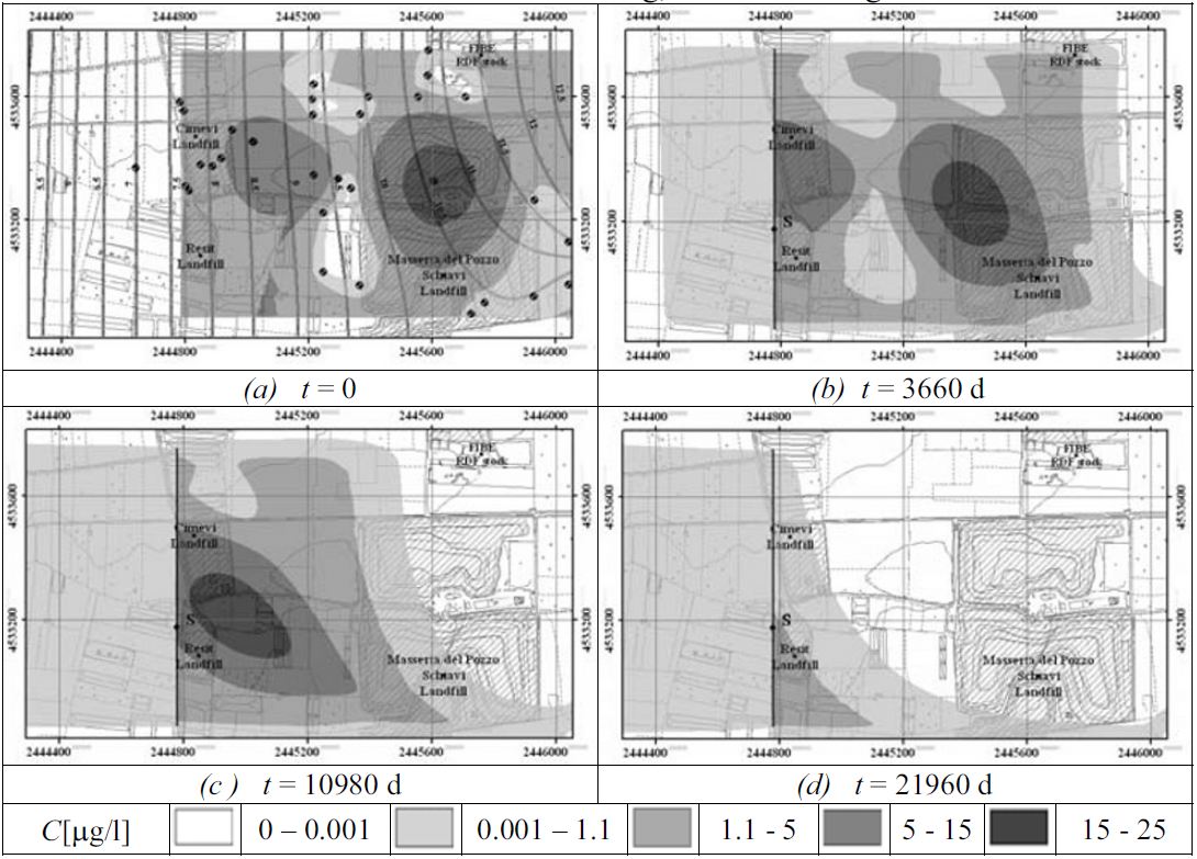
An overview of the contamination flow through the modeled site from the report.
Results
During the numerical run period of about 60 years, the out-flowing concentrations were always lower than the regulatory limit. This result suggests that adsorption barriers can be considered for the remediation of the Campania site. Before implementation, a more thorough investigation is required into some technological aspects, pollutant synergy and long term effects.
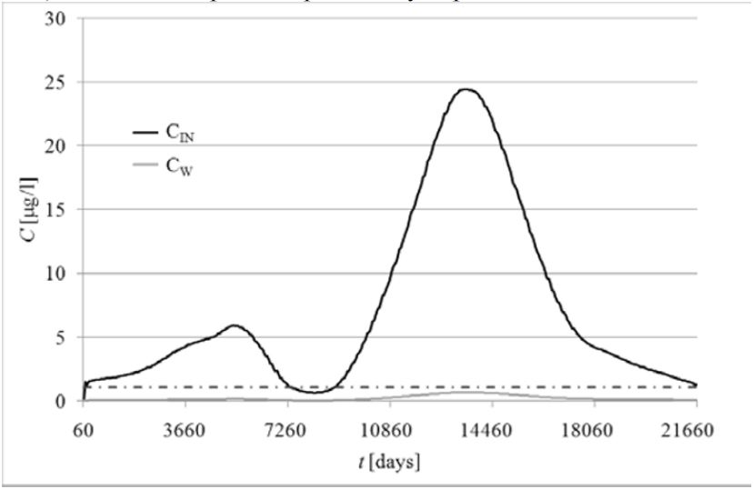
A figure demonstrating the concentrations prior to the barrier (Cin) and the downgradient values (Cw)
Discussion and Conclusions
A problem that the modeling software results showed is that if the inflowing concentrations of the PCE vary, a desorption phenomena may occur within the barrier when the PCE concentrations are lower than equilibrium. A solution to this issue is to use a wider barrier to ensure that a gradual release of PCE occurs, avoiding critical out-flowing concentrations. Therefore the barrier must be designed both to retain intense concentration peaks and to ensure long term performance.
GAC Laboratory and Modeling Case Study
This is a summary of a 2D model study done by F. Di Natale: (Di Natale et al., 2008)
Background and Site Description
A 2D numerical model was created to assess the applicability of using a granular activated carbon (GAC) PRB for the removal of cadmium (Cd(II)) from contaminated groundwater. Laboratory tests were first performed to determine the adsorption characteristics between GAC and Cd(II). This is because “the concentration of ionic species in solution is the driving force of adsorption.” (Di Natale et al., 2008) A series of lab tests were performed and led to an equation relating the adsorption capacity of GAC to concentrations of cadmium, pH, and sodium.
The 2D model used the equation from the laboratory tests and modeled a case study involving a topsoil layer, located near a riverbank, contaminated with Cd(II). A geometric representation of the model of the site is shown in the figure below.
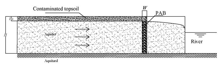
A figure demonstrating the cross-sectional flow through the barrier
Parameters necessary for the model were established, and can be found in the article. Some characteristics included aquifer bed depth, porosity, hydraulic conductivity, topsoil depth and average Cd concentration. The weather was modeled by assuming several intense rainfall periods, that greatly increase the cadmium concentrations in the aquifer to dangerous levels.
PRB Design and computer model
The barrier was designed as a continuous trench, shown in the above figure. The barrier width was determined using an inequality relating groundwater velocity, mass transfer coefficient, and external specific surface of the adsorbent. The width and adsorbent specific surface area must be wide enough for adsorption to occur. This equation can be found in the article.
A first order finite difference implicit scheme was integrated numerically by Fortran and using the SEEP™ code to model the movement of Cd due to advection–dispersion processes. The exact equation can be found in the article.
Results
The simulation results showed that the PRB completely remediated the Cd from the groundwater for the first three months. After the first three months the barrier began to saturate, but sustained an outflow concentration of Cd below 0.005 mg/L for over 7 months. The figure below shows the concentrations of Cd for a 7 month time period.

A figure demonstration the contaminant level over a 7 month period.
The simulation results also showed a peak Cd concentration at the center of the PRB, which the author concluded was due to Cd desorption and resorption when clean groundwater flowed through.
Discussion and Conclusion
The results of the computer model simulation provided insight to the usage of a GAC PRB for cadmium removal. The tendency for the Cd to desorb when exposed to clean incoming groundwater demonstrated that the PRB is self-cleaning. However outflowing Cd concentrations may be present due to the desorption process. The author suggests that the PRB should be utilized to dampen the concentration peaks of a contaminant, as opposed to a full removal technology. With a properly designed barrier the author believes that the PRB can be used to assure compliance with safety regulations and reduce hazardous pollution because the Cd at its highest remained well below the maximum contaminant level.
Limestone Full Scale Case Study
The following is a summary of Bronstein’s findings of the full scale case study: (Bronstein, 2005)
Background and site description
An onsite landfill and surface impoundment was located on a former lead battery recycling center in Nesquehoning, Pennsylvania. This site, owned by Tonolli Corporation, was placed on the NPL list in 1989, because a river located 3 miles downstream of the site contained high concentrations of contaminant As, Cd, Pb, and Cr. Contamination was located 0-19 feet below ground surface and in the alluvium.
PRB design
A pilot scale limestone trench was constructed in August of 1998 parallel to the creek, with dimensions 1400x3x24 feet (LxWxD).
Results
From 2002 data, the trench was found to be effective in reducing Pb concentrations below the performance standards. Cd levels decreased slightly, but remained above the performance standards. The limestone trench seemed to have no effect on the other contaminants.
Discussion and Conclusions
The limestone trench was one of several cleanup remedies, and successfully reduced Pb concentrations. More information can be found on the EPA website.
ORC Column, Batch and Bench Scale Modeling Case Study
The following is a summary of the findings by Yeh, Lin, and Wu: (Yeh et al., 2010)
Background and site description
The authors performed a series of column, batch, and bench scale tests to determine if oxygen releasing compounds (ORC) in a permeable reactive barrier can create enough dissolved oxygen to promote microbial growth. The microbes can then be used to decompose BTEX (benzene, toluene, ethylbenzene, and p-xylene).Testing Design
Column
A column test was first created to justify the use of ORC. 100 g of ORC was used in the column tests and consisted of cement, sand, H2O, KH2PO4, NaNO3, and varying concentrations of CaO2 (10-50%). Cylindrical columns were packed from the bottom as follows: 10 cm of Ottawa sands, 5-10 cm of ORC, and 40 cm of Ottawa sands on top. Perforated stainless steel plates supported the packing media (top and bottom) and bottom of the column. Both K2HPO4 and KH2PO4 regulated the pH and served as nutrient components in the medium.
Batch
A batch test was created to determine the inhibitory concentrations of benzene and toluene, and the required DO needed for microbial growth. The batch test used 5 mL of inoculum in a 100 mL nutrient solution. 5 mL were added to varying concentrations of benzene and toluene, ranging from 20-320 mg/L. The microbial concentration was determined spectrophotometrically initially and after mixing. The DO required was also measured using BOD5 testing guidelines from NIEA.Bench-scale PRB system
The bench-scale PRB is shown in the figure below:
The closed tank was filled with Ottawa sand to a bed depth of 20 cm. The ORC was 2 cm thick and situated 20 cm from the water inlet. The ORC composition consisted of cement, sand 40% CaO2, KH2PO4, K2HPO4, NaNO3, and H2O. Perforated stainless steel plates were placed on either side of the ORC and at the outlet to prevent water channeling. 12 monitoring wells were placed throughout the tank to measure DO, CFU (colony forming units), pH, oxidation-reduction potential (ORP), and BTEX concentrations. The inlet concentrations of benzene, toluene, ethylbenzene and p-xylene were maintained each at approximately 30mg/L. Two BTEX shock loadings were also applied by increasing the concentration to 60 mg/L for 4 hours to test the stability and the recovery capability of the PRB system. According to oxygen-releasing rate estimated in the column experiments, the initial amounts of ORCs were determined. Water samples were collected for BTEX analysis daily, and for DO, CFU, pH and ORP analysis weekly. The microbial communities were analyzed and can be found in the case study.
Results
Column Tests
Varying the CaO2 concentrations allowed for different oxygen releasing rates of the ORC beads, and the results of the tests found that 40% CaO2 provided the greatest oxygen-releasing rate. This concentration was used in the bench scale.Batch Tests
From benzene and toluene concentrations ranging from 20-80 mg/L, the organisms decomposed the contaminants to less than or equal to 5% of residual. The microbes used these compounds as carbon sources to build their own biomass. The highest measured biomass was at 80 mg/L. At high concentrations (320 mg/L) the benzene and toluene inhibited microorganism growth, so 90% residual still remained. The results also indicate that the amount of ORC used provides sufficient oxygen for bacterial growth, and increase the efficiency in decomposing the pollutants.Bench Scale
The test was performed over a 100 day period. There was no reduction in the removal of BTEX during the first shock loading. After the second shock-loading, however, the removal efficiencies of benzene, toluene, ethylbenzene and p-xylene from this system were reduced to 32, 44, 75 and 75%. The pre-shock removal efficiencies were between 10 to 21% greater than the following shock loading, but slowly increased to a stable level.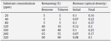
The results showed that aerobic degradation did occur, due to differences between the DO and BTEX concentrations in the influent and effluent.
To provide sufficient oxygen, the ORC was replaced on days 38 and 94.
Discussion and Conclusions
The ORC PRB was successful in providing DO necessary to sustain microbial growth, and successfully reduced BTEX concentrations. The authors further concluded that an ORC can be used for approximately 40 days, but must be replaced after that time period to ensure a sufficient DO.Recommended Reading
This document was developed by the members of the Interstate Technology and Regulatory Council (ITRC) Permeable Reactive Barriers Team. It reviews a variety of aspects of a PRB from treatment processes, to site characterization, design, construction, performance assessment, and considerations.
ITRC. (2005). Permeable Reactive Barriers: Lessons Learned / New Directions.
This article was developed by Kate Bronstein and provides an overview of PRBs as well as covers a variety of case studies.
Bronstein, K. (2005). Permeable Reactive Barriers for Inorganic and Radionuclide Contamination. National Network of Environmental Manegment Studies Fellow.
This document was developed by the USEPA and offers information on PRB technologies.
Permeable Reactive Barrier Technologies for Contaminant Remediation
USEPA (1998) http://www.clu-in.org/download/rtdf/prb/reactbar.pdf
References
- Bronstein, K. (2005). Permeable Reactive Barriers for Inorganic and Radionuclide Contamination. National Network of Environmental Manegment Studies Fellow.
- Courcelles, B. (2012). Radial Filtration in Permeable Reactive Barriers. International Journal of Environmental Pollution and Remediation, 1(1). doi:10.11159/ijepr.2012.015
- Day, S., O’Hannesin, S., & Marsden, L. (1999, June 30). Geotechnical techniques for the construction of reactive barriers. Journal of hazardous materials. Retrieved from http://www.ncbi.nlm.nih.gov/pubmed/10518664
- Di Nardo, A., Di Natale, M., Erto, A., Musmarra, D., & Vortonea, I. (2010). Permeable reactive barrier for groundwater PCE remediation : the case study of a solid waste landfill pollution. ESCAPE20. doi:10.1016/S1570-7946(10)28170-1
- Di Natale, F., Di Natale, M., Greco, R., Lancia, a, Laudante, C., & Musmarra, D. (2008). Groundwater protection from cadmium contamination by permeable reactive barriers. Journal of hazardous materials, 160(2-3), 428–34. Retrieved from http://www.ncbi.nlm.nih.gov/pubmed/18448247
- EPA. (2006). East Helena: Zero-Valent Iron Permeable Reactive Barrier Treatment of Arsenic in Groundwater.
- Gavaskar, A. (1999). Design of construction techniques for permeable reactive barriers. Journal of hazardous materials, 68(1-2), 41–71.
- ITRC. (2005). Permeable Reactive Barriers : Lessons Learned / New Directions.
- ITRC Mining Waste Team. (2005). Permeable Reactive Barrier Systems. ITRC. Retrieved from http://www.itrcweb.org/miningwaste-guidance/to_permeable.htm
- Olson, T. M., & Higgens, M. R. (2009). Life-Cycle Case Study Comparison of Permeable Reactive Barrier versus Pump-and-Treat Remediation. Environmental Science and Technology, 43(24), 9432–9438.
- Richards, P. (2008). Seven‐year performance evaluation of a permeable reactive barrier. Remediation Journal, 18(3), 63–78. Retrieved from http://doi.wiley.com/10.1002/rem.20172
- Thiruvenkatachari, R., Vigneswaran, S., & Naidu, R. (2008). Permeable Reactive Barrier for Groundwater Remediation. Journal of Industrial and Engineering Chemistry, 14, 145–156.
- Tinker Air Force Base. (2006). Tinker View Acres. Retrieved from http://www.tinker.af.mil/library/factsheets/factsheet.asp?id=5591
- U.S. Department of Energy. (2005). Performance Assessment and Recommendations for Rejuvenation of a Permeable Reactive Barrier : Cotter Corporation ’ s Canon City , Colorado , Uranium Mill.
- University of Newcastle Australia. (2012). Georemediation. Retrieved from http://www.newcastle.edu.au/research-centre/cgmm/research/georemediation.html
- Vogan, J. L. (1999). Performance evaluation of a permeable reactive barrier for remediation of dissolved chlorinated solvents in groundwater.
- Wilkin, R. T., Acree, S. D., Ross, R. R., Beak, D. G., & Lee, T. R. (2009). Performance of a zerovalent iron reactive barrier for the treatment of arsenic in groundwater: Part 1. Hydrogeochemical studies. Journal of contaminant hydrology, 106(1-2), 1–14. doi:10.1016/j.jconhyd.2008.12.002
- Yeh, C.-H., Lin, C.-W., & Wu, C.-H. (2010). A permeable reactive barrier for the bioremediation of BTEX-contaminated groundwater: Microbial community distribution and removal efficiencies. Journal of hazardous materials, 178(1-3), 74–80. Retrieved from http://www.ncbi.nlm.nih.gov/pubmed/20122795
 Heidi Pence
  Lauren Zwang
Industry News


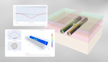
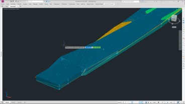
Enable true ground-informed design in Civil 3D

Events

19th European Conference on Soil Mechanics and Geotechnical Engineering, Istanbul, Türkiye
The 10th International Congress on Environmental Geotechnics

11th European Conference on Numerical Methods in Geotechnical Engineering

1st International Conference on Sustainability in Geotechnical Engineering (ICSGE 2027)

The 4th International Conference on Press-in Engineering 2027 (ICPE2027)

International Symposium on Cone Penetration Testing (CPT'27)

Rocscience International Conference 2027: Geotechnics, Structures & Hydro in the Age of AI
IS-GI Lyon 2027: International Symposium on Ground Improvement


4 COMMENTS
Carl Elder*
Mar, 28, 2013 Heidi and Lauren,Thank you for the informative review of PRB. You report was well organized and easy to read. I particularly like your use of figures and diagrams to support information provided in the text. Your review of PRB case studies was excellent, and in particular, I enjoyed seeing a range of contaminant/materials presented. Your sections on the history of PRB and construction methods were also very good. I do however, believe that the chemistry section could use a bit more work. Below are several thoughts for you to consider for your report.
- In the chemistry section, I recommend that you add discussion about the abiotic reduction of chlorinated organics, specifically PCE and TCE by ZVI. This is a very common use for ZVI PRBs and should be included.
- Your chemistry section mentions that PCE is treated in a ZVI PRB by absorption. The treatment mechanism is actually a reduction reaction where the iron is oxidized as the PCE is reduced. Sequential reduction of PCE through TCE, cDCE and vinyl chloride to ethene is a key concept. This topic is covered in several EPA/RTDF documents such as http://www.clu-in.org/download/rtdf/prb/reactbar.pdf .
- In the Applicable Soil section, you may wish to mention that some soils are geochemically incompatible with reactive barriers, depending on the reaction. For example, sites having soil that is high in naturally-occurring arsenic are a poor choice for a ZVI PRB or anaerobic-biological PRB because arsenic is mobilized in a reducing environment. Similarly, PRBs that manipulate pH must be carefully thought through to avoid the leaching of contaminants from the formation under a different pH.
- I disagree with your statements that “most inorganic contaminants themselves are elements and cannot be broken down but can only change speciation”. All organic contaminants are compounds composed of one or more carbon plus other elements (i.e., CH4 is one of the simplest organic compounds and consists of four atoms and two elements). Metals that contaminate aquifers and soil tend to be elements such as chromium, arsenic, lead, etc. These are often treated by adjusting their valence (which in turn can change their phase from aqueous to precipitate or vice versa).
- The equation describing the width of a barrier is for an adsorptive media. Reactions for some wall, such as ZVI PRBs are first order so the required width varies logarithmically since C/Co = exp(-kt) where C is concentration, k is the reaction rate and t is residence time in the PRB (and proportional to groundwater velocity and barrier width).
- On installation methods, continuous trenching equipment is now available by DeWind. Installation by continuous trenching has many advantages over traditional methods and should be noted.
- In your disadvantages section, I would discuss how the width of a PRB is based on very simple hydraulics. Specifically, the groundwater velocity is a key input to the calculation of barrier width. However, natural aquifers have hydraulic conductivities, and hence groundwater velocities, that can vary by orders of magnitude. Selecting an appropriate factor of safety for PRB design amidst this level of variability has been a significant challenge for PRB design.
Lauren Zwang
Apr, 21, 2013 Dear Carl,Thank you very much for your input. We have responded to these comments in the appropriate sections within our paper.
Best,
Heidi and Lauren
Edit Comment
Sally Simpson*
Apr, 05, 2013 Heidi and Lauren,excellent job on the review. I wanted to know what the current understanding is with regards to the long-term behavior of the permeable reactive barriers. Are they becoming clogged up as you indicated in one of your case histories or in general that is not a problem? Are they only a short-to-mid-term solution? A few pointers on that, maybe even a section discussing this, would be great. Thanks!
Heidi Pence
Apr, 21, 2013 Dear Sally,Thank you for this question. We have added a paragraph on the status of long-term performance in the disadvantages section.
Best,
Heidi and Lauren
Edit Comment