Contents [show]
- Introduction
- Applicable Soils
- Construction Procedures
- Vibroflot
- Design
- Cost
- Case Study: Densifying Sands Near Existing Structures
- Case Study: Vibroflotation for Densification of Hydraulic Fill
- Case Study: Compaction of Reclaimed Soil through Vibroflotation
- Case Study: International Mineral and Chemical Corporation Phosphate Plant
- Case Study: Effectiveness of Vibroflotation on Silty Sand
- References
Introduction
Loose soils are a well documented problem, common in the construction industry. Immediate settlements of 1 inch per foot (depth) of loose sand can occur in worst-case scenarios. Contractors have two main options: use deep foundations to bypass the unfavorable layers, or use a compaction technique to improve the site conditions (D’Appolonia, 1954). Vibroflotation was first used in Germany in the 1930s and first appeared in the United States in 1948 when the Bureau of Reclamation studied the possibilities for sand and silt compaction at the site of the Enders Dam in Nebraska (D’Appolonia, 1954).
The term vibroflotation is often used interchangeably with vibrocompaction in the literature. However vibrocompaction is a broader term that encompasses two different techniques. The first is vibroflotation, which uses a vibroflot that vibrates horizontally. The second utilizes a vibrating probe which vibrates vertically. It should be noted that vibroflotation is used as a mechanism for implementing vibro-replacement, a method which combines the technique of vibroflotation with gravel backfilling in order to create stone columns. This is a review of vibroflotation only.
Vibroflotation utilizes horizontal vibrations in conjunction with fluid to reduce the interparticle friction of the surrounding soil. This allows the material to densify and creates a column with improved engineering characteristics, including an increase in strength and a reduction in compressibility. Figure 2 displays the transition of soil from a loose state to a dense state. The goal of vibroflotation is to increase the relative density of a soil. This increase in relative density results in reduced settlements as well as improved resistance to liquefaction.

Figure 2: Densification of soil during vibroflotation (Bauer Maschinen GmbH, 2012)
Several factors, including the equipment size and quality, spacing and pattern, in situ material, vibroflot withdrawal technique, backfill material, and workmanship greatly affect the level of density achieved during vibroflotation (Brown, 1977).
Applicable Soils
The suitability of site conditions is the most important factor when considering vibratory compaction as a solution. Most coarse-grained soils with fines content of less than 10% are considered acceptable for this method, i.e. sands, gravels, and slags. A grain size distribution showing the range of applicable soils is presented in Figure 3. Vibroflotation has been found to work best for loose granular materials located below the water table.

Figure 3: The orange area represents the grain size distribution of soils suitable for vibroflotation (Bauer Maschinen GmbH, 2012)
Clay layers, excessive fines content and organics can all cause serious complications when attempting to improve a site with vibroflotation. These materials generate excess pore water pressures which greatly inhibits volume change and results in preventing the granules to move into a denser state. To accomodate some of these issues, "earthquake drains" is a possible solution for sites which are susceptible to liquefaction (Rollins et al, 2003). The vibrations are also significantly damped in the presence of these soils, and reduces the radial densification dramatically. If the in situ material particle size is too great, the penetration of the vibroflot is greatly hindered which increases the amount of time needed to achieve adequate compaction. This can make the technique very expensive (Brown, 1977).
In order to accurately depict the site characteristics through grain size distribution, sieve tests are needed in order to assess a large number of samples. A good alternative to this method is the use of the cone penetration tests (CPT). The results from a CPT offer a continuous soil profile at each location and measures variations through correlations in soil strength, compressibility and hydraulic conductivity if the piezocone is used (Massarsch, 2005).

Figure 4: CPT applicability (Massarsch, 2005)
Construction Procedures
The vibroflot is inserted into the ground and typically can be used to improve soil up to depths of 150 feet. Vibroflotation utilizes water and the mechanical vibrations of the vibroflot to move the particles into a denser state. Typical radial distances affected range from 5 to 15 feet (Bauer Maschinen GmbH, 2012).
The vibroflot is suspended from a crane and seats on the surface of the ground that is to be improved. To penetrate the material, the bottom jet is activated and the vibration begins. The water saturates the material to create a “quick sand” condition (i.e. temporarily liquefying the material), which allows the vibroflot to sink to the desired depth of improvement. At that point, the bottom jet is stopped and the water is transferred to the upper jet. This is done to create a saturated environment surrounding the vibroflot, thereby enhancing the compaction of the material. The vibroflot remains at the desired depth of improvement until the material reaches adequate density. The density of the soil is measured by using the power input (via the electric current or hydraulic pressure) as an index. As the material densifies, the vibroflot requires more power to continue vibrating at which point an ammeter or pressure gauge displays a peak in required power.
Once this point is reached, the vibroflot is raised one lift (generally ranging from 1 to 3 feet) and compaction ensues until the peak amperage or hydraulic pressure is reached once again. A figure of the successive steps is provided in Figure 5. The peak power requirement can be correlated to the density of the soil, so an accurate measurement of the in situ density can be recorded.

Figure 5: Vibroflotation construction sequence (Bauer Maschinen GmbH, 2012)
As the procedure continues, a large crater is created at the surface which must be backfilled, as seen in Figure 5. Roughly 5 cubic feet of backfill material is needed for every foot that is compacted by vibroflotation (D’Appolonia, 1954). Acceptable backfills include gravel or sand with minimal fines content, or material from onsite with a fines content of less than 6% (Bauer Maschinen GmbH, 2012). Slag has been used in some cases, and can be an economical option if there is a large supply available. The gradation of the backfill is the most important factor controlling the speed at which the backfill reaches the void created by the vibroflot. The suitability number gives an index for the quality of the backfill material. It is calculated as:

Equation 1: Suitability number (Brown, 1977)
Where D50, D20, and D10 are the grain size diameters (in millimeters) at 50%, 20%, and 10% passing, respectively. Brown described suitability numbers in the range of 1-10 to be excellent, while numbers greater than 50 are considered unsuitable (Brown, 1977).
Coarser material generally makes better backfill material, however, if the particle size is too large, it can become stuck between the crater and the vibroflotation apparatus, preventing it from reaching the desired depth. It should be noted that vibroflotation generally does not work for surface materials (uppermost 2 to 3 feet of material) and instead a roller is needed to attain equivalent compaction.

Figure 6: Crater created due to vibroflotation method (Bauer Maschinen GmbH, 2012)
Close attention and observation of the process is critical throughout the implementation of vibroflotation. If the addition of backfill material is stopped or reduced, the vibroflot may become “starved.” When this occurs, the vibroflot vibrates in the hole without contacting the surrounding material, and thereby reducing compaction effort. This can happen when a hole collapses and cuts off the supply of backfill material to the vibroflot, workers stop moving backfill into the hole, the probe is extracted too quickly, or when the wash water flow is too great and prevents the backfill from falling (Brown, 1977).
Quality Control
During the process, it is important to ensure that the technique is operating efficiently and effectively so that low soil densities are not discovered after completion of the site improvement. Like many construction activities, quality control is very important during construction. Several aspects can be monitored during implementation, including penetration depth, penetration rate, withdrawal rate, proper probe location, volume of added backfill, backfill gradation, ammeter or hydraulic pressure peak, and vibroflot operating frequency.
Upon the conclusion of vibroflotation activities, densities are usually checked to ensure that adequate compaction was achieved. While the standard penetration test (SPT) was the most used and available method for doing this, it gave a poor measure of bearing capacity and relative density. Today, CPTs are most commonly used for verifying relative density. Relationships have been developed which correlate CPT results to relative density.
Vibroflot
The module which vibrates and compacts the surrounding material is known as the vibroflot. Vibroflot dimensions and vibrating capabilities vary by manufacturer and are often modified by contractors to suit their intended purpose. As part of quality assurance, it is important to verify that the vibroflot mobilized is the one pretedermined, since minor variations can greatly affect performance.
Though dimensions vary, generally they are 7 feet or greater in length, and rely upon an electric motor or hydraulic power to generate the desired vibratory forces. The vibratory forces are generated by a rotating eccentric shaft with frequencies ranging from about 2000 to 3000 revolutions per minute. The vibroflot is made up of two sections: the vibrator and the follow-up pipe. The vibrator typically weighs on the order of 10,000 to 20,000 pounds and generates a centrifugal force of 43,000 to 70,000 pounds (Bauer Maschinen GmbH, 2012). There are multiple water discharge points along the apparatus, one of which is near the top (the upper jet) and one at the base (the bottom jet). The follow-up pipe remains nearly stationary during operation and acts as a rigid casing, providing protection to the power and water supply. Figure 7 below provides a cross-section and typical dimensions of the device.

Figure 7: Vibroflot cross section (D’Appolonia, 1954)
Design
It is necessary to plan the vibroflotation so that the desired compaction and uniformity is achieved throughout the site. Material compaction is measured in terms of relative density. This is calculated as:

Equation 2: Relative density (D’Appolonia, 1954)
Currently, 80 percent is the general criterion for compaction; this level of compaction is generally deemed acceptable for soils beneath foundations. However, this number can vary considerably from project to project depending on site and project requirements (Bauer Maschinen GmbH, 2012).
Spacing distance and pattern affects the uniformity of the densified material. Typical patterns include square, triangular, and line and spacing distances range between 5 and 10 feet. Typical spacing patterns are presented in Figure 8. Rectangular and square patterns are used to improve soil beneath spread footings or for small isolated areas of improvement. Equilateral triangle patterns are the most efficient and are commonly used in scenarios with large areas. It has been observed that square patterns require about 5-8% more probe locations to achieve densities equivalent to equilateral triangular patterns (Brown, 1977).

Figure 8: Vibroflotation example patterns (Brown, 1977)
Design spacing distance is a function of desired relative density, grain size distribution of the material, fines content, and power capabilities of the vibroflotation device. The spacing is chosen so that improved columns from each probe location overlap. The effectiveness of the process decreases exponentially as the radial distance from the vibroflot increases. To determine a suitable spacing, an arbitrary number called an influence coefficient is determined based on the compaction in relation to the radial distance from the probe location. The influence coefficient is a function of distance and relative density for one vibroflotation probe location, and increases as the distance to the probe decreases. For considered design patterns, the influence coefficients are displayed around the probe location and represent an equivalent value at the corresponding radial distance. The critical point is determined based on the greatest distance from the surrounding probe locations. The sum of the coefficients from each of the probe locations must be greater than the required minimum coefficient value. Figure 9 from the International Mineral and Chemical Corporation Phosphate Plant case study shows the sum at the critical point, A, is calculated as 4 + 4 + 4 = 12. For this project, a minimum influence coefficient was determined to be 10, based on achieved relative density. A value of 12 shows that this design spacing is adequate (D’Appolonia et al., 1953).

Figure 9: Triangular spacing pattern showing sum of influence coefficients at critical point A (D’Appolonia et al., 1953)
Correlating CPT Results to Relative Density
As noted in the section on 'Quality Control,' the CPT is the most common form of verification testing used today. Data obtained from CPTs is used to measure the relative density of the improved soil. Accurately estimating relative density from CPT results is critical to ensuring the vibroflotation process has achieved the desired densification results.
Research in large calibration chambers has yielded several correlations between cone penetration resistance and relative density. Two of these correlations discussed by Robertson, et al. (1997) are be presented below. It is important to note that most of the testing results used in the development of these correlations was performed on un-aged, clean, fine to medium, uniform silica sands. Site-specific testing is crucial in developing representative relationships for soil at a site. However, large calibration chamber testing is expensive and often not implemented on projects, this can result in problems later during the verification stage.
The research completed through verification testing has shown that cone penetration resistance is controlled by soil density, sand compressibility, and vertical and horizontal effective stresses. Sand compressibility has been shown to be especially important. Robertson, et al. (1997) discussed a review of calibration chamber test results that demonstrated a lower cone penetration resistance for high compressibility sands compared to low compressibility sands for a constant relative density. Figure 10 below shows the relationship between relative density and cone resistance for sands of different compressiblities.

Figure 10 : Relationship between relative density and cone penetration resistance for sands of different compressibilities (Robertson et. al, 1997)
The first correlation is presented below (Equation 3) is based on calibration testing of Ticino sand, which considers the effects of compressibility and effective vertical stress, was developed by Baldi et al. (1986).

Equation 3: Relative density and cone penetration resistance correlation (Baldi et al, 1986)
In this correlation, C0, C1 and C2 are soil constants whose values can be seen in Figures 11 and 12. The cone penetration resistance is represented by qc and is in units of kilopascals, as is the effective vertical stress, σ'. This correlation was used to develop Figures 11 and 12, which show the relationship between vertical effective stress and cone resistance for both normally consolidated and overconsolidated Tocino sands.
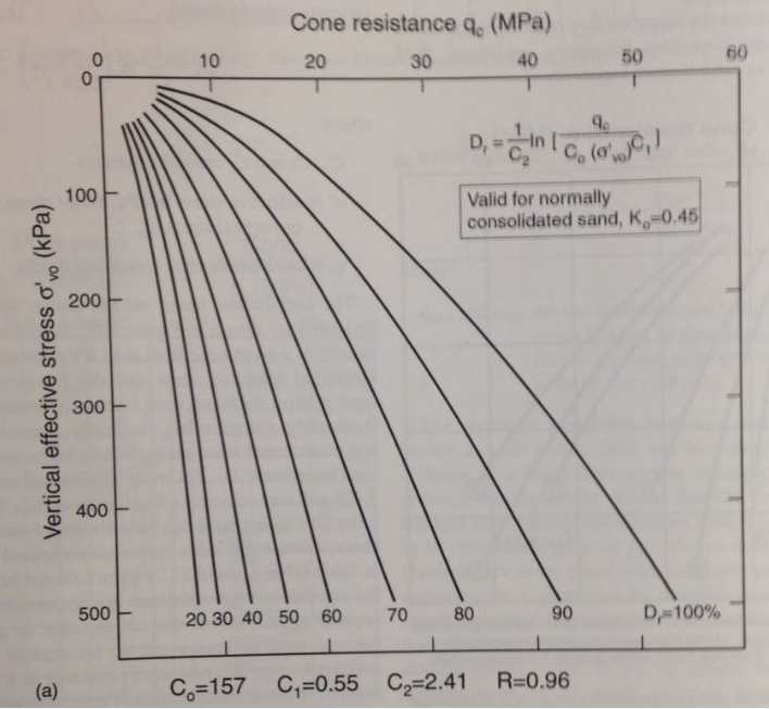
Figure 11: Relationship between Dr, qc, and σ' for normally consolidated Tocino sands (Robertson et. al, 1997)

Figure 12: Relationship between Dr, qc, and σ' for normally and over consolidated Tocino sands (Robertson et. al, 1997)
The second correlation presented (Equation 4) was developed by Kulhway and Mayne (1990).

Equation 4: Relative density and cone penetration resistance correlation (Kulhway & Mayne,1990)
Here qc is the penetration resistance, σv' is the effective vertical stress, Pa is atmospheric pressure, OCR0.18 is the overconsolidation factor, QA is the ageing factor and QC is the compressibility factor whose value ranges from 0.9, for low compressiblity sands to 1.09, for high compressiblity sands.
It is important to reiterate that the correlations presented above are based on testing performed on un-aged, clean, medium to fine, uniform silica sands. These correlations may be appropriate to apply to reasonably similar soils, however, site-specific calibration testing is crucial for producing accurate and reliable relative density correlations from CPT results.
Cost
In one case study, vibroflotation was found to be one of the most economical remedial solutions compared to other common ground improvement techniques. Concluded in 1999, the study examined possible design solutions for Croton Dam, which was found to be susceptible to damage due to earthquake shaking. Although, it is located near Muskegon, Michigan, it is considered a “high-hazard” dam so it must be designed to account for large ground accelerations. The dam consists of two earth embankments, a gated spillway, and a concrete and masonry powerhouse. The earth embankments are composed of a hydraulically placed sand fill with concrete cores. A seismic analysis of the embankments found that they were likely to liquefy in the event of a magnitude 6 or greater earthquake. It was determined that adequate strength to resist liquefaction could be achieved by compaction (Uddin & Baltz, 2004). Table 1 displays the possible remediation techniques examined in this study, along with associated costs. Compared to the other two ground improvement methods (jet grouting and compaction grouting), vibroflotation proved to be the most economical solution for this case.

Table 1: Comparison of costs at Croton Dam (Uddin & Baltz, 2004)
The three ground improvement techniques examined (vibroflotation, jet grouting, and compaction grouting) were quoted by contractors based on the “maximum plausible area” of improvement. This was taken to be 70% of the maximum possible area of improvement. While vibroflotation was judged to have the greatest increase on material strength, it was also considered to cause significant damage to existing surficial structures (Uddin & Baltz, 2004).
Case Study: Densifying Sands Near Existing Structures
Vibroflotation for Ground Improvement (Sreekantiah, 1993)
Background
The Mangalore Chemicals and Fertilizers Company Limited is situated on the West Coast of India in Mangalore, Karnataka. The company desired to install new machinery at their existing location. In order to install the new machinery, the very loose granular soil which comprised the site had to be improved in order to achieve adequate bearing capacity as well as to assure that settlements of the soil where the new machinery was to be installed would be within permissible limits.
The company is located on a site that originally consisted of agricultural land. In 1966, the ground level elevation, which was originally 6 feet above sea level, was raised through dredging. The soil used for dredging was recovered during the construction of the New Mangalore Port on the West Coast of India.
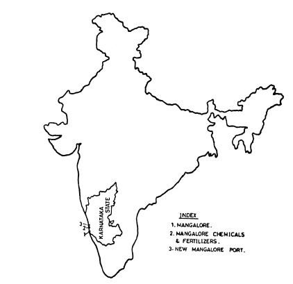
Figure 13: Mangalore location (Sreekantiah, 1993)
Site Characteristics
The subsurface soil on the site was comprised of the soil that had been dredged in 1966. The profile consisted of two layers: a clean sand layer underlain by a clay layer with consistency that varied from soft to stiff throughout the site.
Standard and cone penetration tests were performed throughout the site in order to the assess the subsurface soil conditions. The clay layer was determined to be a marine clay with varying consistency. The upper sand layer consisted of a stratum varying from fine sand to sandy gravel with N values ranging from 1 to 16. Rock was found at depths ranging from 92 feet to 98 feet below ground elevation.
Statement of Problem
The Mangalore Chemicals and Fertilizers Company site posed a great challenge. The use of a shallow foundation to support the machines that were to be installed proved unfeasible. However, the use of traditional driven piles was also not feasible because construction disturbance posed a risk of damage to the nearby existing machinery at the site.
Solution and Design
Bored compaction piles were one of the alternatives considered for increasing bearing capacity of the subsurface soil. However, difficulties were encountered during construction of the bored piles. Additionally, the load tests performed on the bored compaction piles proved unsuccessful. The expected applied loads from the machinery proposed to be installed on the site ranged from 229 pounds per square inch to 236 pounds per square inch. By virtue of the limiting site conditions, ground improvement by vibroflotation was determined to be the best course of action.
A thorough analysis of the subsurface soils was conducted in order to determine whether vibroflotation would be a feasible improvement technique. The upper sand layer was determined to contain less than 10 percent fines making it ideal for improvement by vibroflotation. An area of 79 feet by 20 feet was selected to be compacted to a desired depth of 23 feet below ground elevation.
CEM-INDIA performed the work, electing a wet process using a standard vibroflot with a 15.75 inch diameter, 26.5 feet length and a weight of 6750 pounds. A square grid spacing scheme of 6.5 feet by 6.5 feet centre to centre was implemented. The vibroflot was inserted at intervals of 6.5 feet to the desired depth and was removed in 9.6 inch intervals. The criteria provided for acceptance in the contract with CEM-INDIA was a maximum acceptable settlement of 0.47 inches for a 6.2 feet diameter plate under a pressure of 65 pounds per square inch. Additionally, a static cone penetration test resistance of 22 pounds per square inch had to be achieved post compaction.
Results
After compaction was completed, the site was tested for the previously stated criteria. Five of the eight load tests performed on the improved area resulted in a settlement of less than 0.47 inches, while two load tests resulted in a settlement of less than 0.60 inches and one resulted in a settlement of 1.6 inches. The static cone penetration test resistance of 2175 pounds per square inch was generally achieved and demonstrated that between depths of 6.5 feet and 23 feet penetration resistance achieved a threefold to fivefold increase post compaction, as can be seen below in Figure 14. Raft foundations were selected for use on the improved site area. Foundation settlement was monitored after the installation of the new machinery and was determined to be within permissible limits.
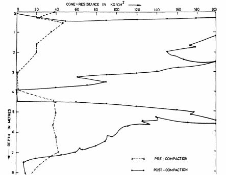
Figure 14: Mangalore CPT results (Sreekantiah, 1993)
Conclusions
The installation of new machinery on an existing site posed challenges. The subsurface soil which was comprised of granular soil underlain by a clay layer made the use of shallow foundations unfeasible. However, the risk of potential damage to nearby existing machinery due to disturbance caused by construction made traditional driven piles also unfeasible. Vibroflotation proved to be a successful technique for improving the ground on site. It densified the soil which resulted in an increased bearing capacity as well as reduced settlement to permissible limits. Vibroflotation was the best technical and economical solution for improving the loose granular soil without posing a great risk to existing structures and machinery near the site.
Case Study: Vibroflotation for Densification of Hydraulic Fill
Application of Vibro Techniques for Infrastructure Projects in India (Sharma, 2004)
Background & Site Characteristics
The Seabird Naval Base at Karwar in the Indian state of Karnataka required the construction of a breakwater structure over a distance of more than 3 miles. The existing seabed was composed of clay and soft silt. In order to create favorable soil conditions for construction of the breakwater, the existing seabed was dredged to a depth of nearly 20 feet. Hydraulic sand fill obtained from nearby borrow pits was used to the backfill the dredged area.
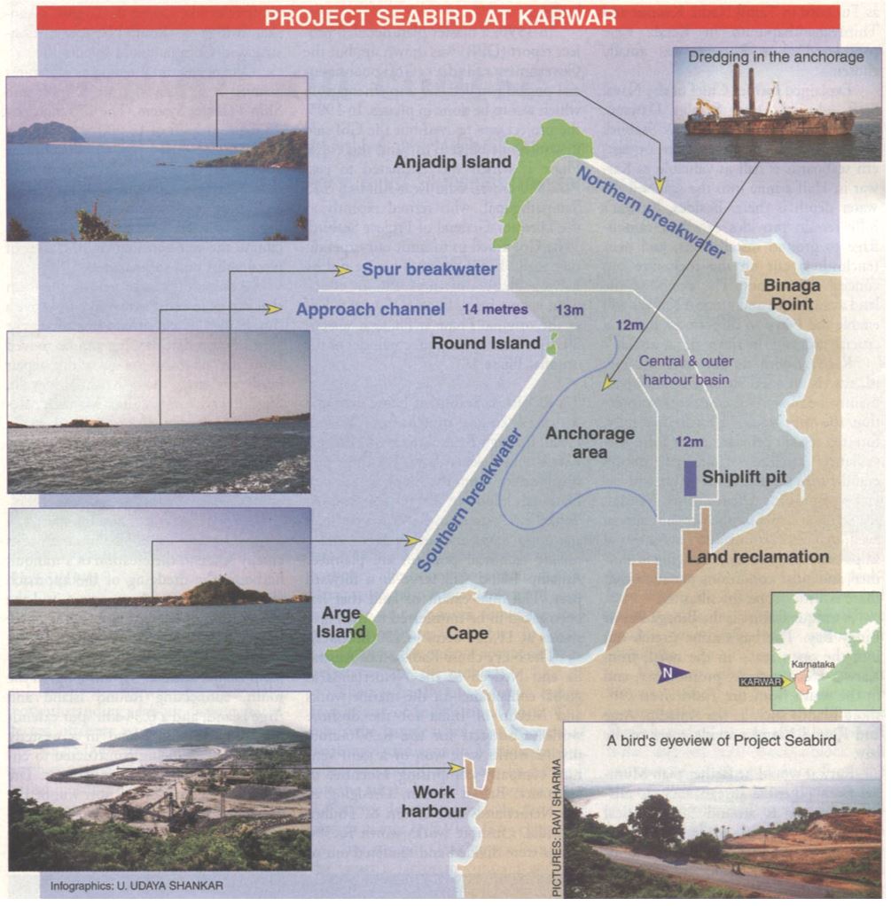
Figure 15: Project Seabird (Sharma, 2004)
Statement of Problem
After the hydraulic fill was placed, cone penetration tests were performed to assess the conditions of the sand fill. The tests revealed the need for compaction of the top 13 feet of the fill in order to reduce potential settlements and mitigate liquefaction potential.

Figure 16: Project Seabird soil profile (Sharma, 2004)
Solution and Design
Vibro compaction is a technique commonly used to densify hydraulic fills in offshore projects. For the construction of the breakwater structure at the Seabird Naval Base an area of about 35 acres was selected to be compacted to a depth of about 13 feet.
Keller Grundbau performed the work over a period of 10 working months. The equipment setup included the use of four 49 foot long vibrators suspended from a crane situated on a barge in order to allow for the compaction of the soil beneath 33 feet of seawater. The spacing scheme selected was a 9.8 foot by 9.8 foot center to center grid.
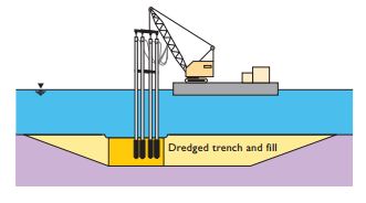
Figure 17: Project Seabird setup (Raju et al., 2003)
Results
Seven days after compaction was completed, cone penetration tests were performed every 164 feet along the breakwater structure. The results demonstrated that the 13 feet of compacted fill achieved a twofold to threefold increase in penetration resistance compared to the uncompacted values. Settlement was monitored after the construction of the breakwater and range between 0.65 feet and 0.98 feet.
Conclusions
Offshore densification of hydraulic fills can be a challenging task. Vibro flotation proves to be an easily implemented and economical technique for performing the necessary ground improvement. The results from the use of vibro flotation at the Seabird Naval Base in Karwar support this. Vibro flotation densified the hydraulic fill beneath the breakwater structure which increased the penetration resistance of the fill and reduced future settlements.
Case Study: Compaction of Reclaimed Soil through Vibroflotation
On - and Offshore Vibro-Compaction for an Oil Pipeline in Singapore (Wehr & Raju, 2002)
Background
Jurong Island is a man made island that was formed from the combination of seven islands southwest of the main island of Singapore. The installation of a crude oil pipeline on the island mandated the densification of the existing sandfill in order to reduce future settlements beneath the pipeline as well as to stabilize the seaside slope of the sand embankment adjacent to the pipeline jetty.
Site Characteristics
Jurong Island is an artificial island made of reclaimed soil. The reclaimed soil consisted of medium to coarse sand with fines contents less than 5 percent, making it ideal for vibroflotation. The groundwater table was found approximately 16 feet below the ground level surface.
Cone penetration tests were performed both in the area where the pipeline was to be installed as well as at the sand embankment at the pipeline jetty. Cone penetration resistances ranged from 725 pounds per square inch to 1160 pounds per square inch with friction ratios of approximately 0.5 percent.
Statement of Problem
Based on the results from the cone penetration tests, it was evident that densification of the reclaimed soil would be necessary in two areas. The area beneath where the pipeline was to be installed required densification in order to reduce potential settlements. The area of the sand bund where the pipeline jetty was to be located also required densification in order to reduce settlements and stabilize the adjacent seaside slopes. The project posed a unique challenge in selecting the ground improvement method to be used. The method selected had to be of minimal disturbance to nearby areas because of an existing gas pipeline situated approximately 6 feet to 10 feet below the ground surface. This was especially crucial in the area where the crude oil pipeline and the gas pipeline were to cross.
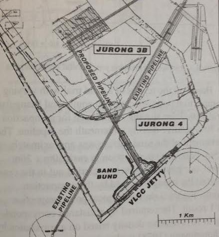
Figure 18: Jurong Island site layout (Wehr & Raju, 2002)
Solution and Design
Beneath the proposed pipeline, an area of nearly 2.8 miles in length and 65 feet in width was selected for compaction to 70 percent relative density. Based on field trials, an equilateral triangular scheme with 11.5 foot spacing was selected. The area of the sand bund where the VLCC (very large crude carrier) jetty was to be located required offshore compaction spanning a distance of over 3200 feet in length and 65 feet in width. This area was also compacted to 70 percent relative density using the same 11.5 foot equilateral triangular spacing scheme. The slope adjacent to this area had slopes of 1:3, vertical to horizontal. A 13 foot equilateral triangular spacing scheme was utilized at the inclined slopes in order to achieve ISO/IEC JTC specifications for compaction of inclined slopes. A crane situated on a barge was used for offshore compaction.
Results
Post compaction cone penetration tests were performed throughout the improved areas. The criteria requiring 70 percent relative density in all areas of the project was achieved without any major issues. Additionally, vibration measurements were carried out to assure there wasn’t any damage to the existing gas pipeline. Measurements showed maximum particle velocities well within permissible limits.
Conclusions
The densification of reclaimed soil both on and off shore on Jurong Island was achieved through the use vibroflotation. Vibroflotation was an appropriate method for this project because of its relatively low cost, on and off shore flexibility as well as its low disturbance level during construction when compared with other techniques.
Case Study: International Mineral and Chemical Corporation Phosphate Plant
Vibroflotation Compaction at Thermalito Afterbay (Harder et. al., 1984).
Background
The construction of Thermalito Afterbay Dam in Northern California was completed in 1967. In August of 1975 an earthquake of magnitude 5.7 revealed an active fault that had not been previously detected. As a result of the rupture of the Cleveland Hill Fault during the 1975 earthquake, the Department of Water Resources evaluated the embankments resistance to liquefaction under a 6.5 magnitude earthquake. Their analysis predicted that the silty sand layers in the foundation of the embankment would liquefy entirely under these seismic conditions and would result in failure of the dam. In 1979 storage restriction of the reservoir was implemented in order to reduce risk of failure until the seismic evaluation was completed. The need to restore the dam to full operation was evident and therefore numerous remedial methods for stabilization of the dam were considered at Thermalito Bay.
Site Characterisitics
The embankment was 8 miles long with a maximum height of 39 feet. The foundation consisted of several layers of different soils including clay, silt, sand and gravel. The surface layer throughout most of the embankment was composed of a clay and silt layer several feet thick. The silty sand layers which were targeted for densification contained a median of 15 percent fines, with 30 percent of the samples containing more than 20 percent fines. The groundwater table downstream of the dam was found at a depth of 5 feet to 10 feet.
Statement of Problem
The seismic evaluation performed predicted that the silty sand layers of the embankment foundation would liquefy entirely under an earthquake of magnitude 6.5. Densification of these silty sand layers was necessary to mitigate liquefaction risks. A primary concern when selecting the remedial method to be used at the site was assuring that the clay embankment would not be at risk of large settlements or heaves during treatment.
Solution and Design
A vibroflotation testing program using 100 horsepower vibroflot was performed on the embankment in order to determine the effectiveness of vibroflotation in densifying silty sand. Two worksites were selected to assure a range of conditions were represented in the testing program. However, this vibroflot was not used to penetrate the clay and silt surface layer. Instead pre-drilling with a 24 inch bucket auger was used to create holes that reached the silty sand layers. These holes were then backfilled with sand before the vibroflot was inserted. An equilateral triangular spacing scheme was utilized with spacings ranging from 6.5 feet to 9.5 feet. Table 2 summarizing the vibroflotation test program and variables can be found below.

Table 2: Thermalito Bay worksites table (Harder et. al., 1984)
Results
Standard and cone penetration tests were performed before and after the vibroflotation testing program was performed at the embankment. SPT blow counts and CPT resistance at both sites showed generally no change before and after compaction. SPT and CPT results for worksite 2 can be seen below and demonstrate the ineffectiveness of vibroflotation testing program.

Figure 20: Thermalito Bay CPT and SPT results (Harder et. al., 1984)
Conclusions
Based on the results of the vibroflotation testing program at Thermalito Afterbay we can conclude that vibroflotation is not an effective method for the densification of silty sands below a cohesive soil cap. The failure of vibroflotation as a technique in this case is most likely due to the relatively high fines content of 15 percent in the silty sand layer. Generally, vibroflotation is ideal for sands with less than 10 percent fines content.
Case Study: Effectiveness of Vibroflotation on Silty Sand
Vibroflotation Compaction at Thermalito Afterbay (Harder et. al., 1984).
Background
The construction of Thermalito Afterbay Dam in Northern California was completed in 1967. In August of 1975 an earthquake of magnitude 5.7 revealed an active fault that had not been previously detected. As a result of the rupture of the Cleveland Hill Fault during the 1975 earthquake, the Department of Water Resources evaluated the embankments resistance to liquefaction under a 6.5 magnitude earthquake. Their analysis predicted that the silty sand layers in the foundation of the embankment would liquefy entirely under these seismic conditions and would result in failure of the dam. In 1979 storage restriction of the reservoir was implemented in order to reduce risk of failure until the seismic evaluation was completed. The need to restore the dam to full operation was evident and therefore numerous remedial methods for stabilization of the dam were considered at Thermalito Bay.
Site Characterisitics
The embankment was 8 miles long with a maximum height of 39 feet. The foundation consisted of several layers of different soils including clay, silt, sand and gravel. The surface layer throughout most of the embankment was composed of a clay and silt layer several feet thick. The silty sand layers which were targeted for densification contained a median of 15 percent fines, with 30 percent of the samples containing more than 20 percent fines. The groundwater table downstream of the dam was found at a depth of 5 feet to 10 feet.
Statement of Problem
The seismic evaluation performed predicted that the silty sand layers of the embankment foundation would liquefy entirely under an earthquake of magnitude 6.5. Densification of these silty sand layers was necessary to mitigate liquefaction risks. A primary concern when selecting the remedial method to be used at the site was assuring that the clay embankment would not be at risk of large settlements or heaves during treatment.
Solution and Design
A vibroflotation testing program using 100 horsepower vibroflot was performed on the embankment in order to determine the effectiveness of vibroflotation in densifying silty sand. Two worksites were selected to assure a range of conditions were represented in the testing program. However, this vibroflot was not used to penetrate the clay and silt surface layer. Instead pre-drilling with a 24 inch bucket auger was used to create holes that reached the silty sand layers. These holes were then backfilled with sand before the vibroflot was inserted. An equilateral triangular spacing scheme was utilized with spacings ranging from 6.5 feet to 9.5 feet. Table 2 summarizing the vibroflotation test program and variables can be found below.
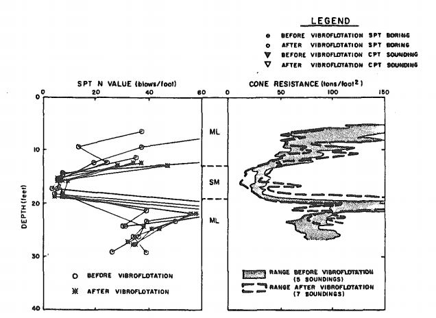
Table 2: Thermalito Bay worksites table (Harder et. al., 1984)
Results
Standard and cone penetration tests were performed before and after the vibroflotation testing program was performed at the embankment. SPT blow counts and CPT resistance at both sites showed generally no change before and after compaction. SPT and CPT results for worksite 2 can be seen below and demonstrate the ineffectiveness of vibroflotation testing program.
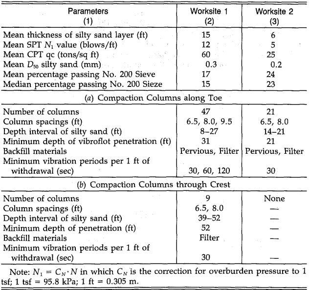
Figure 20: Thermalito Bay CPT and SPT results (Harder et. al., 1984)
Conclusions
Based on the results of the vibroflotation testing program at Thermalito Afterbay we can conclude that vibroflotation is not an effective method for the densification of silty sands below a cohesive soil cap. The failure of vibroflotation as a technique in this case is most likely due to the relatively high fines content of 15 percent in the silty sand layer. Generally, vibroflotation is ideal for sands with less than 10 percent fines content.
References
- Bauer Maschinen GmbH. (2012). “Ground Improvement by Depth Vibrator.” PI 80, Schrobenhausen, Germany.
- Bo, M.W., Arulrajah, A., Horpibulsuk, S., Leong, M., & Disfani, M.M. (2013). “Densification of Land Reclamation Sands by Deep Vibratory Compaction Techniques.” J. Mater. Civ. Eng. ASCE.
- Brown, R.E. (1977). "Vibroflotation compaction of cohesionless soils." J. Geotech. Eng. Div. ASCE, 103(12), 1437-1451.
- D'Appolonia, E., Miller Jr., C.E., & Ware, T.M. (1953). "Sand Compaction by Vibroflotation." Proc., ASCE, 79(200), 1-23.
- D’Appolonia, E. (1954). “Loose Sands- Their Compaction by Vibroflotation.” Symp. on Dynamic Testing of Soils, ASTM Int., 138-162.
- Harder, L.F., Hammond, W.D, & Ross, P.S. (1984). “Vibroflotation Compaction at Thermalito Afterbay.” ASCE, New Orleans, LA, 57-70.
- Lunne, T., Robertson, P.K., & Powell, J.J.M. (1997). "Interpretation in Coarse-Grained Soils." Cone Penetration Testing in Geotechnical Practice, Blackie Academic & Professional, London, 81-85
- Massarsch, K.R. & Fellenius, B.H. (2005). “Deep Vibratory Compaction of Granular Soils.” Ground Improvement: Case Histories, B. Indraratna & J. Chu, eds., Elsevier, Amsterdam, 539-561
- Raju, V.R., Wegner, R., & Veltriselvan, A. (2003) “Application of Vibro Techniques for Infrastructure Projects in India.” Proc. of the Indian Geot. Conf., Roorkee, India.
- Rollins, K.M., Anderson, J.K.S., McCain, A.K., & Goughnour, R.R. (2003). "Vertical Composite Drains for Mitigating Liquefaction Hazard." Proc. Thirteenth Int. Offshore and Polar Eng. Conf., Int. Soc. Offshore and Polar Eng., Honolulu, HI, 498-505.
- Sharma, Ravi (2004). “Seabird on Course.” Bharat Rakshak.
- Sreekantiah, H.R. (1993). “Vibroflotation for Ground Improvement - A Case Study.” Third Int. Conf. on Case Histories in Geot. Eng., St. Louis, MO, 949-954.
- Uddin, N. & Baltz, J.F. (2004). “Seismic Evaluation and Remediation of Croton Dam.” Waterpower 1999, ASCE.
- Vibroflotation Group. (2014). “Vibroflotation.”(Apr. 6, 2014).
- Wehr, W.C.S. & Raju, V.R. (2002). “On- and Offshore Vibro-Compaction for an Oil Pipeline in Singapore.” Proc., Int. Conf. on Vibratory Pile Driving and Deep Soil Compaction, Louvain-La Neuve, Belgium, 129-132.
 Ian McCreery
  Yanet Zepeda
Industry News

Rockfall prevention project at Bozeman, MT


Rockfall Mitigation Project in West Virginia

Events

12th International Symposium on Field Monitoring in Geomechanics 2026

DFI 50th Anniversary Conference on Deep Foundations

9th International Symposium for Geotechnical Safety and Risk

5th International Symposium on Frontiers in Offshore Geotechnics (ISFOG)

Pan Mediterranean Geotechnical Engineering Conference

The Third Vietnam Symposium on Advances in Offshore Engineering

4th Asia-Pacific Conference on Physical Modelling in Geotechnics (ACPMG 2024)

The 2nd GeoMandu: Geotechnics for Sustainable Infrastructures

5th International Conference on Transportation Geotechnics


18 COMMENTS
Chris Arnott*
Apr, 09, 2014 'reduce settlement' is a little bit of an over simplification. the targeted aim of VC is to increase relative density/reduce void ratio in order to reduce settlements. Remember that the reason that resistance to liquefaction is improved is also due to the increase in relative density. Yanet Zepeda
Apr, 30, 2014The reviewer is correct in noting that while reducing settlement is one of the results of implementing vibroflotation, the targeted aim is to increase the relative density of the soils. Amendments have been made to the introduction section reflecting this.
Edit Comment
Chris Arnott*
Apr, 09, 2014 A significant issue in current major projects in the middle east is corelating CPT values to relative density in order to assess achieved values. This issue can be mitigated by undertaking calibration chamber testing at the outset of a project to develop site specific relationship between the two rather than reverting to out-dated academic references which are almost exclusively based on silica sands from other parts of the world. it is worth notign that calcareous soils or soils prone to crushing behave significantly differently to non-crushable soils and while reduction factors exist the most appropriate way to monitor this is through pre-start calibration testing in the laboratory. unfortunately this testing is not cheap and is more often than not overlooked leading to techcnial disputes at the verification stage (ive been involved in these disputes onmy last two projects!) Yanet Zepeda
Apr, 30, 2014The reviewer has noted a very important issue in the process of quality assurance of vibroflotation. A discussion on correlating CPT results to relative density has been added to the 'Design' section in order to address this issue.
Edit Comment
Chris Arnott*
Apr, 09, 2014 The single most important activity is the VC trial. I cant stress enough how much performance varies between contractors and their differen vibroflots. on my current project I've had 5 different companies working the same type of fill with wildly different outcomes. In soem cases contractors have had to demobilise after completion of the trial as their equipment was not capable of achieveing the required criteria. trials must be QA/QC very closely and the method statement agreed with the engineer/client ahead of commencement.In my experience CPTs are easily the most common form of verification tesing with boreholes undertaken far less frequencies (not at all in some cases) more so for sample collectin to monitor fill chareacteristics are remaining consistent i.e. grading. My previous project the spec called for post VC CPTs every 900m2 with a BH every 25,000m2. As commented earlier the issue with CPTs is converting the reported cone resitance value (Qc) to a relative density in order to assess performance against a relative density verification criteria.
Yanet Zepeda
Apr, 30, 2014The reviewer is correct in stating that CPTs are the most common form of verification testing used today. The section on 'Quality Assurance' has been updated to reflect this.
Edit Comment
Chris Arnott*
Apr, 09, 2014 Beware the vibroflot data sheet! Every contractor has reinvented the wheel and modified for their own purpose. Question number 1 at a project kickoff meeting, is the contractor mobilising the flots he said he would. performance can vary wildly with only minor changes in specification. Yanet Zepeda
Apr, 30, 2014The reviewer notes the importance of assuring the predetermined vibroflot is the one mobilized on site due to the great differences in performance that minor changes to the dimensions and capabilities can make. The 'Vibroflot' section has been updated.
Edit Comment
Chris Arnott*
Apr, 09, 2014 Compaction criteria differ from project to project with some engineers preferring certain approaches over others in their specification. The lack of a standardised approach in this regard is significantly harming the industry as disputes rage both during and after works, contesting that criteria was not achieved or criteria was not appropriate. I have come across 65% relative density, 60% RD, Emax/min values, 25mm settlement from 200kPa embankment load test and even 95% MDD which is impossible to verify and needs several iterations of analysis to check. As follow on contractors take ownership of improved areas of ground as easy way to achieve variations can be to claim that the ground has not been improved to the level suitable for their own works. Clients can dispute the iterations undertaken by their contractors to calculate any one of the above criteria from CPT Qc values. The setting out of an auditable acceptance criteria, the agreement of its iteration and the placement of this information into tenders of partues expected to use the site at a later date is fundamental to success but is too often not achieved. Yanet Zepeda
Apr, 30, 2014The comment of the reviewer is valid and has been addressed within the text.
Edit Comment
Chris Arnott*
Apr, 09, 2014 A good attempt at summarising vibroflotation although the difference between vibrocompaction and ibroflotation could have been explored to defintively define which activity was being reviewed. More importantly this approach of inviting industry based reviews is an excellent program and kudos to whomever is responsible. There are many of us in the industry who would love to be engaged by students in order to share our experiences and develop the engineers of the future. the authors are welcome to contact me further at [email protected] with any further queries although i caveat that i am far from an expert, i may be able to point them in the direction of some however ;)well done to all and good luck!
Chris Arnott
Yanet Zepeda
Apr, 30, 2014Thank you for taking the time to review our project and for providing helpful feedback as well as resources for improving and updating our project. A section has been added to the introduction in order to more clearly distinguish between vibroflotation and vibrocompaction.
Edit Comment
Hassan Ghafouri*
Apr, 11, 2014 is it vibro replacement or vibro compaction? Yanet Zepeda
Apr, 30, 2014Thank you for taking the time to review our project and for providing helpful feedback. Our review is of the method of 'Vibroflotation.' A section has been added to the introduction in order to more clearly distinguish between vibroflotation, vibrocompaction and vibro-replacement.
Edit Comment
Kiki*
Apr, 17, 2014 Congratulations! Mr Arnott's point on CPT and relative density correlations is crucial. Have you came across any empirical correlations of that kind?Another aspect in liquefaction remediation projects is the depth of compaction combined with the intensity of seismic motion reaching the soil surface.
Improving the entire liquefiable stratum may not always be ideal, since in that case, seismic motion propagates all the way up to the soil surface.
Ian McCreery
Apr, 30, 2014Thank you for taking the time to review our project. We have updated the report and added a section titled “Correlating CPT Results to Relative Density” which is in the Design section. This section discusses two methods for correlating CPT results with relative density, along with other issues.
You make a good point regarding the importance of designing for the depth of improvement while considering the intensity of the seismic motion in order to appropriately mitigate liquefaction.
Edit Comment
Armin Stuedlein*
Apr, 23, 2014 Overall, a nice introduction to the vibro-methods. I’m sure you have both learned a good deal. Generally speaking, a description between vibrocompaction (i.e., vibroflotation), and vibro-replacement would have been good. Another general comment is that you try to incorporate newer findings from the recent research that has been conducted. Recent references appear limited to manufacturer-contractor sources, and these sources of information tend to be limited in technological scope (for proprietary / market edge reasons). Thank you for the opportunity to review your work – good luck in the class! Some detailed comments follow:Applicable soils:
The comments “Clay layers, excessive fines content, cementation, and organics can all cause serious complications when attempting to improve a site with vibroflotation. These materials fill the voids between larger particles and cement the materials together, thereby greatly inhibiting the ability of the granules to move into a denser state. The vibrations are also significantly damped in the presence of these soils, and reduce the radial densification dramatically."
Seems ambiguous and questionable. I don’t quite think fines “cement” soil particles together. The main problem is that these materials generate positive excess pore pressures, and these pore pressures hinder volume change. A reference to the recent work by Kyle Rollins on using Wick Drains (PVDs) between the stone columns would be in order here – reducing pore pressures in materials with 20% fines or more tends to improve the amount of densification achievable.
Quality Control
General comment: I think the reference “Brown 1977” has been used too much. There is a state-of-the-art report by Jim Mitchell from 1981 that would have provided some more information. The CPT is now much more favored, nearly forty years after Brown 1977. Also, excess pore pressures will affect both CPT and SPT, and in fact any measure of stiffness or strength. A discussion on the time effects is significantly warranted here – particularly with regard to fines, but also in general. See and reference Slocombe et al (2000).
References:
Mitchell, J.K. (1981) “Soil Improvement--State-of-the-Art Report,” Session 12, Proceedings of the Tenth International Conference on Soil Mechanics and Foundation Engineering, Stockholm, Vol. 4, pp. 506-565.
Slocombe, B.C., Bell, A.L., and Baez, J.I. (2000) “The Densification of Granular Soils Using Vibro Methods,” Geotechnique, Vol. 50, No. 6, Thomas Telford Ltd., London, UK
Design:
Although it is nice to target a relative density, it is often extremely difficult to determine the in-situ relative density, particularly with fines present. Hence the need for in-situ testing. A discussion on design for liquefaction mitigation is in order, perhaps with regard to the incremental change in (N1)60,cs or CPT tip resistance required to move from one side of the liquefaction triggering curves to the other.
Case histories:
The reference to Harder et al. 1994 is good. A follow up with the descriptions of Rollins’ recent work would be good here, to show that advances have been made since 1984….
Ian McCreery
Apr, 30, 2014Thank you for taking the time to review our project and offering your feedback. As this project just focuses on vibroflotation, we have added to the introduction clarifying the scope.
Several of the resources that were used are outdated, but offer some basic information about the method that is still relevant. To improve the report, we utilized two additional resources, which provide additional information regarding correlations between CPT results and relative density, and the use of drains to accommodate sands with higher fines contents. These sources are listed as references 7 and 10, respectively.
Regarding the comments on Applicable Soils: the reviewer is correct in noting that the term “cement” was used incorrectly. This has been corrected and this section has been modified to accurately describe the problems that are due to a high fines content.
Regarding the comments on Quality Control: the reviewer raises a valid point, and the corresponding sections have been updated to correct the mistakes. Unfortunately, we were unable to acquire the suggested resources prior to the deadline of this project.
Regarding the comments on Design: a section titled “Correlating CPT Results to Relative Density” has been added under the Design section. This section discusses the importance of adequately correlating the CPT results to relative density.
Edit Comment