Contents [show]
- Description
- Background
- Applicability
- Process
- Field Setup
- Advantages
- Limitations of the Technology
- Economic and Regulatory Considerations
- Case Study I: Hanford Tank Waste Treatment and Immobilization Plant (the Vit Plant)
- Case Study II: Parsons Chemical /ETM Enterprises Superfund Site (USEPA, 1997c)
- Recommended Reading
- References
Description
Vitrification is the transformation of a substance into a glass. This is usually achieved by heating to high temperature and rapid cooling. In geoenvironmental engineering, soil vitrification is a method that embeds the waste into a glassy matrix so that hazardous waste will not leak out. It requires high temperature to melt the soil. The melted soil is then refrozen into glass-like solid. The contaminants are incorporated into the waste glass either through chemical bonding or through encapsulation (USEPA, 1992a). Glass-forming additives are usually added to form the glassy matrix. Since the glass-like solid is chemically inert and has low leaching characteristics, it has superb performance in isolating the waste from the environment. Therefore, soil vitrification is a method that has been widely used to treat hazardous and radioactive waste. Soil vitrification is also effective for organic waste because the high temperature will make organics inactivated.
Background
Amorphous materials usually have a glass transition temperature, below which the material behaves like glass. (Figure.1) Crystals is able to behave like glass under rapidly cooling too. If the cooling process takes place in a short time, molecules are not able to form crystalline structures. Instead, they remain in disordered structures as in liquids, forming glassy materials.
Figure.1 Illustration of Vitrification (Penn State University)
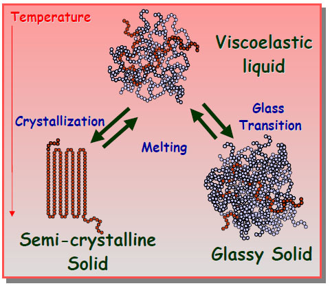
At molecular scale, take water as an example, when water freezes, water molecules form covalent bonds and hydrogen bonds, forming ice crystals. However, if glass-forming additives were added, they can prevent water molecules from forming ordered crystal structures. As the temperature decreases, the velocities of water molecules are reduced. When the motion of molecules stops, they remain disordered, which is called a “glass”. The difference between frozen and vitrified liquid can be visualized in Figure.2. Glass has high strength and is chemically stable. The strength of the vitrified product can be 5 to 10 times of that for unreinforced concrete in both tension and compression. From stoichiometric point of view, vitrified products can absorb into their structure varying concentrations of a wide variety of different foreign elements. These advantages make soil vitrification effective in waste treatment.
Figure.2 Difference between Frozen and Vitrification (University of Southern Mississippi)

Applicability
Soils
Soil vitrification is applicable to any type of soil, however, it is not usually used on soil with high water content. The reason is only the cost. For moist soil, water needs to be evaporated before the vitrification process begins. The energy cost is increased at high water content. If vitrification is to be performed within aquifers, contaminants may flow to other places due to diffusion, which is another issue that needs to be considered. Also, the volume of the waste to be vitrified cannot be infinit. If the wastes are too deep or the soil contains too many voids, in-situ vitrification would be more difficult.
Types of Contaminants
As described before, due to the high strength, low leaching characteristics and inert chemical properties, vitrification is good for hazardous, radioactive and organic contaminants as well as heavy metal. It can certainly be used to treat other types of contaminants if necessary.
Waste Streams
- Sludge or filter cake, composed of metal hydroxides, carbonates, nitrates, or silicates;
- Ion exchange resins, inorganic filter media,zeolites;
- Asbestos or glass fiber fillers;
- Incinerator ash and off-gas liquor;
- Soils and geologic materials;
- Concrete;
- Radioactively contaminated materials;
- Chemical process wastes;
Process
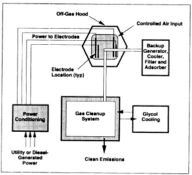
Soil vitrification can be performed both in-situ and ex-situ. In-situ vitrification (ISV) uses electrical power to heat and melt soil, sludge or sediments. Then the molten material is cooled to form the vitrified product. The vitrified monolith is usually left in place after treatment. However, if onsite disposal is not allowed, the vitrified monolith should be excavated and removed. A gas-effluent treatment system is required to collect and treat the gas produced by high temperature. Two electrodes need to be inserted into the soil to perform vitrification. To allow the current to flow through the soil, there has to be sufficient monovalent alkali cations to provide needed electrical conductivity. If the soil does not meet the requirement, fluxing materials containing cations should be added to the base material. Since dry soil has high electric resistance, the applied voltage needs to be very high (as much as several thousand volts) at the beginning to overcome the resistance. Once the soil is molten, the mobilization of ions will increase the conductivity and reduce the resistance of soil. Therefore, at steady state, the voltage will reduce to several hundred volts. The current will be increased to maintain steady power supply. The ISV device is illustrated in Figure. 3.
Figure.3 In-situ Vitrification (EPA, 1994)
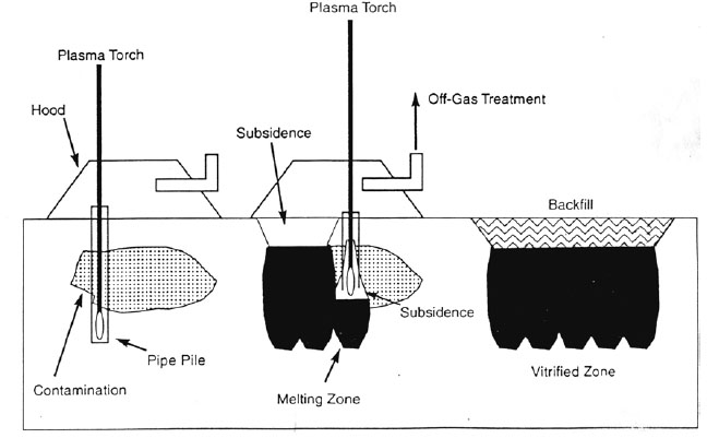
An alternative technique of in-situ vitrification is called in-situ plasma vitrification (ISPV). Instead of using traditional electrodes, ISPV uses a plasma torch to melt the contaminated soil. The plasma torch is able to create temperatures ranging from 4000 to 7000 degrees Celsius. It is rapid, inexpensive and efficient. The procedures of ISPV are similar to ISV. The only difference is the method of melting the soil. The ISPV device is shown in Figure.4. (Circeo and Martin, 1997)
Figure.4 In-situ Plasma Vitrification (Circeo and Martin, 1997)
Soil vitrification process is seldom studied quantitatively. However, there is a mathematical model to predict vitrification time, depth, width and electrical consumption for ISV (Koegler and Kindle, 1991). The model has been developed at Pacific Northwest Laboratory as a predictive tool to assist engineers and researchers in the application of ISV to different sites. The model is based on energy balance, which means that electrical energy is converted into heat in the molten glass through resistance. The heat loss is taken into account by empirical measurements. With certain increment in depth, the model is able to calculate the corresponding increment in the width of the vitrified product. Figure. 5 shows a sample result of the model. The model output reaches a high agreement with the actual shape of the vitrified product.
Figure.5 Comparison of Model Output with Actual Melt Shape (Koegler and Kindle, 1991)

Ex-situ vitrification treats contaminated soil in special reactors. The theory is similar to in-situ vitrification. The difference is that the waste needs to be excavated prior to treatment. The process of ex-situ vitrification varies for different technologies used. Several technologies have been developed as described in (Staley, 1995).
Figure.6 is an advanced multifuel-capable combustion and melting system developed by Vortec Corporation, which is an example of the ex-situ vitrification equipment. It uses high efficiency combustion of fossil fuels in cyclonic flow to rapidly heat and melt contaminated soil. Contaminated soil and, if needed, glass-forming additives, are preheated in a cyclonic flow precombustor. Combustion and melting are completed in a counter rotating vortex combustion unit. Melting is completed in a cyclone melter. Slag is separated from combustion gasses at the exhaust of the cyclone melter and is removed from the CMS and allowed to cool. Exhaust gasses are treated via electrostatic precipitation to remove particulate prior to being released to the atmosphere. The addition of glass-forming additives to the process enhances the products of the vitrified product (Staley, 1995).
Figure.6 Vortec Vitrification System (Staley, 1995)

Field Setup
The vitrification process, when properly designed and executed, produces a product, which is highly stable and leach resistant. Though still at its early development stage, feasibility of various kinds of vitrification process has been examined in laboratory. After demonstrating success of process in the lab and in pilot scale, the field examination and setup could be developed, in which chemical and physical fundamental process firstly have to be conducted. Actually, it has been used more and more in the field.
Fundamental Processes
In general, vitrification treatment includes chemical incorporation and physical encapsulation of contaminants via pyrolysis or combustion, and volatilization of contaminants followed by their removal in the off-gas treatment system (USEPA, 1992a).
Chemical immobilization is achieved when contaminants are chemically bonded into the waste glass product. This is achieved primarily for metals and other inorganic contaminant.
Physical immobilization of contaminants is achieved through encapsulation of the contaminant in the waste glass product. This is the primary method for the remediation of heavy metal contaminants and the nonmetallic inorganic contaminants.
Thermal and chemical processes are the primary means of remediating organic contaminants and volatile inorganic contaminants when using a vitrification process. These processes include pyrolysis, combustion, and volatilization (USEPA, 1992a).
Organic contaminants that are vaporized but not thermally decomposed in the melt are remediated either through combustion or are removed in the off-gas treatment system. Metals, such as mercury, after being volatized during the vitrification process must also be treated via removal in the off-gas treatment system (USEPA, 1995b).
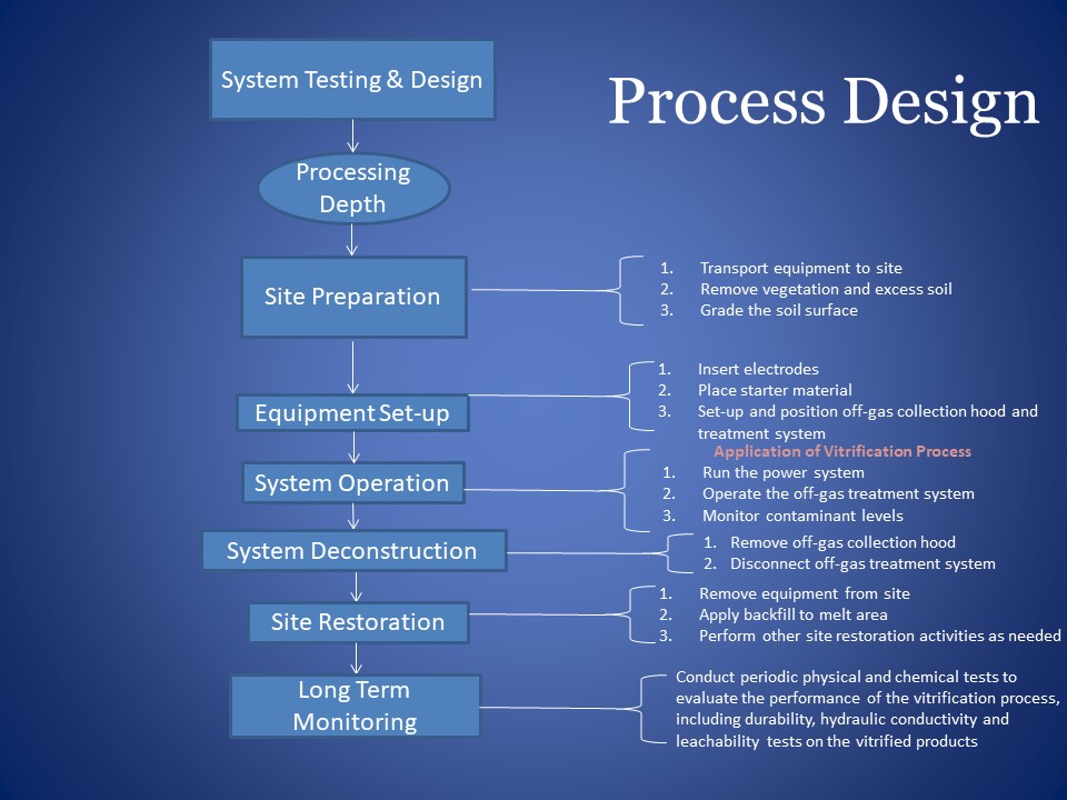
General Design Approach
There are three primary processes for general vitrification design: Treatability testing/bench-scale testing, engineering-scale testing, and pilot- and large-scale testing. The treatability testing is to demonstrate the applicability of technology to the specific soil/waste combinations at the site. The purpose for pilot-scale testing is to confirm that bench-scale testing results will be applicable on a larger scale. Engineering-scale testing is one of the primary developmental tools for ISV. It can test new concepts at a reduced cost while maintaining a high level of confidence in its predictive capabilities for larger-scale operations (USEPA, 1992a).
Figure 7. Field Set-up Design Process
Advantages
The Environmental Protection Agency has declared vitrification to be the “best demonstrated available technology” for heavy metals and high-level radioactive waste (Meegoda and Ezeldin, 2003). It’s a good option especially for disposal of fly ashes containing heavy metals, highly toxic materials, nuclear and radioactive wastes, etc. The advantages of vitrification could be recognized by several aspects, regarding to its durability, high applicability to lots of kinds of soils and contaminants, volume saving, and cost effectiveness.
Stability and Durability
Vitrification technology enables contaminated waste to be stabilized in a glass-like form, for which durability issue is of great importance. Waste glass products always have stable chemical and physical properties and excellent weathering properties. Ewing and Haaker’s (1979) tested the long-term stability of vitrified glass products, using naturally occurring analogues for comparison. Durability tests have also been conducted by Pacific Northwestern National Lab, (PNNL, 2005). The durability of vitrified glass products was predicted to be as high as obsidian. According to the results, vitrification can lock dangerous contaminants, especially radioactive waste in glass forms for thousands of years (PNNL, 2005). Considering vitrifying MSW ashes, if left untreated, landfilled MSW ashes can leach unacceptable levels of As, Br, Cd, Cl, Cr, Cu, F, K, Mo, Na, Pb, S, Sb, Zn, chlorinated dioxins and benzofurans. Sewage sludge can also leach As, Cr and Se (Bingham and Hand, 2006). Leaching from vitrified wastes is generally much lower than from comparable untreated wastes. In the leaching test, the heavy metal releases tended to be lower than required by regulations, with durability in alkali and acidic solutions remaining constant as well (Scarinci and Brusatin, 2000).
Volume Reduction
A major attractive aspect of vitrification is that it can bond a wide variety of toxic species into glass matrix at atomic level and usually with a significant reduction of waste volume. Generally, vitrification leads to significant volume reduction by 25~50% for most natural soils (USEPA, 1997e). Research indicated that volume reduction factor (VRF) was at low level for vitrification, e.g. it was only around 1.2-2.4 according to vitrification method for non-combustible wastes (Park and Moon, 2007). Generally, it’s desirable to exclude the bulky cavities from a volume reduction and waste form quality perspective. Research indicated that there are few bulky cavities in glassy waste forms, which resulted in a high volume reduction.
When dealing with incinerator ashes wastes, comparisons of overall volume reduction compared to other stabilization strategies shows that vitrification reduces the stabilized volume by 96% (Jantzin and Pickett, 1993).
Cost Effectiveness
Vitrification technology is a cost-effective method for difficult sites with mixed contaminants or stringent cleanup standards. The major costs of vitrification operation are electrical power, labor, and consumable materials. The cost of vitrification can at first be slightly higher than other conventional waste disposal technologies. However, the high expenses at first stage will be offset by the savings from storage costs resulting from long-term durability and in volume reduction (up to a 97% reduction in volume compared to the most commonly used alternative) (Meegoda and Ezeldin, 2003).
Other Advantages
- Ability to process a variety of waste types
- Potential reuse of the waste glass
- Good acceptance of ISV, which requires no excavation, transport, or reburial of contaminated soil, improving worker safety and reducing costs
Limitations of the Technology
The size of a melt which can be generated is limited to approximately 40 feet by 40 feet and a maximum depth of about 20 feet with the current ISV technology. The maximum ISV depth obtainable is influenced by several factors, including spacing between electrodes, amount of power available, variations in soil composition and depth to groundwater, soil permeability within an aquifer, and waste and soil density. All of these controlling factors cause a high complexity of in-situ vitrification field set-up.
Soil water content and water recharge can also limit ISV applicability. Extra energy input is needed when dealing with wet soil, to dry the soil prior to melting. This extra energy input could increase the cost of remediation by 10 percent. Therefore, ISV is more economical to implement when the soil to be vitrified has low moisture content.
Because vitrification technology is more often used in situ, it may not be appropriate for sites where contaminated soil exists directly to buildings, other structures, or the property line. Staging or the use of insulating refractory walls can be used in some cases, but will probably increase the costs.
The treatment soil is limited to a maximum of seven to ten percent organics by weight for effective remediation using the current off-gas treatment equipment. It’s ineffective to process contaminated soils containing more than 10% total organic content (USEPA, 1995b).
It is more difficult and unsafe to process sites with flammable liquid or vapor in sealed containers beneath the soil surface. Combustible materials may also present treatment difficulties since the sudden release of gases may exceed the heat load and volumetric capacity of the off-gas treatment system, resulting in a loss of hood vacuum and a potential for fugitive emission releases.
Furthermore, to form a melt, sufficient (typically 2 to 5 percent) monovalent alkali cations (e.g., sodium and potassium) must be present to provide the degree of electrical conductivity needed for the process to operate efficiently. Also it requires sufficient glass-forming materials (e.g., silicon and aluminum oxides) be present within the waste materials to form and support a high-temperature melt. If the natural soil does not meet these requirements, fluxing materials could be added to the base materials, leading to a increasing costs.
Economic and Regulatory Considerations
Cost Estimations
Depending on the size of operation, operating costs in 1994 were estimated at $100-200 per ton of dry waste (Bingham and Hand, 2006). A US Navy study on vitrification of hazardous waste using a melting system found capital and installation costs to be US$2-2.5 million. Operating costs ranged from $100-420 per ton, including labor, fuel and maintenance. Vitrification costs may reasonably be expected to be in the range US$100-500 per ton of remediated materials.
Total cost of vitrification treatment composes of a variety of aspects, site activities, labor, power charge, etc. Overall cost varies among different vitrification techniques, Table 1.
Table 1. Cost estimation of sample ISV (Source: USEPA 1992a)
| Year | Cost range ($/ton) |
| 1965 | $117-165* |
| 1966 | $96-210* |
| 1988 | $163-349* |
| 1989 | $166-175* |
| 1990 | $103-382* |
| 1991 | $360-390* |
| *Calculated from reported figures assuming 1.2 tons/yd3. | |
Several factors determine the overall cost of implementing an ISV system. The primary factors affecting ISV operating costs are the cost of electricity at the site, depth and rate of treatment, and soil moisture content. For recent years, the operation cost for a typical ISV system is in the $360 to $500 per ton range. However, the total costs depends on other factors such as treatability/pilot testing, site preparation, mobilization, and site restoration and long-term monitoring (USEPA, 1997d).
When treating sites with waste materials which need only one remediation technology, vitrification may not be the ideal method, due to its higher unit operational cost comparedto other technologies, Table 2. However, when dealing with sites with waste or contaminated soils that need multiple remedial technologies, vitrification could be the most cost-effective method.
Table 2. Cost comparison of selected soil technologies (modified Grubb and Sitar, 1995)
| Technology | Operational Cost ($/m3) |
| Bioremediation | 20-80 |
| Permeable Reactive Walls | 65-130 |
| Water Flooding | 65-130 |
| Soil Vapor Extraction | 65-130 |
| Radio Frequency Heating | 85-210 |
| Soil Flushing | 100-160 |
| Air Sparging | 100-160 |
| Electro-osmosis | 100-200 |
| Electrokinectics | >17/Mg |
| Vitrification | 300-650 |
Regulatory Considerations
The primary regulatory concerns related to an ISV system are the emissions of the off-gas treatment system during ISV operations, the wastewater generated during off-gas treatment, and the stability and reduced toxicity of the resulting vitrified product.
Federal environmental regulations that are particularly pertinent to ISV system include:
- The comprehensive Environmental Response, Compensation, and Liability Act (CERCLA)
- The Resource Conservation and Recovery Act (RCRA)
- The Clean Air Act (CAA)
- The Safe Drinking Water Act (SDWA)
- The Toxic Substances Control Act
- The Occupational Safety and Health Administration Regulations
State and local regulatory requirements could be more stringent, thus must also be addressed by remedial managers.
Case Study I: Hanford Tank Waste Treatment and Immobilization Plant (the Vit Plant)
The Hanford Vit Plant is being built in southeastern Washington State by the Bechtel National, Inc. Once completed, it will be the world’s largest radioactive waste treatment plant. It will process and stabilize 56 million gallons of radioactive and chemical waste. The radioactive waste to be treated is a byproduct of national defense plutonium-production efforts during World War II and the Cold War. More than one-third of the waste have already leaked, contaminating the subsurface and the river nearby. As introduced before, soil vitrification is an effective method of treating radioactive waste. In this plant, waste will be blent with glass-forming materials and heated to more than 1100 degrees Celsius. The mixture is then poured into stainless steel canisters to cool and solidify, which makes it stable and impervious. Then the vitrified waste within the canisters can be disposed permanently and safely. The radioactivity will safely dissipate over hundreds to thousands of years.
There used to have nine former nuclear reactors and associated processing facilities at the location of the Hanford Site. From 1944 to 1987, these reactors were used to produce materials for atomic weapons associated with America's defense program. The reactors generated billions of gallons of liquid waste and millions of tons solid waste that must be cleaned up.
The plant includes four major nuclear facilities, which are pretreatment, low-activity waste vitrification, high-level waste vitrification and the analytical laboratory. The project is challenging because the magnitude of the treatment plant is very large. It requires more than 260000 cubic yards of concrete, 40000 tons of structural steel and nearly 1 million feet of piping.
The waste will be delivered from the underground storage tanks to the Vit Plant through a series of underground transfer lines. The "pipe-in-pipe" system ensures that there are no leaks of materials during the transfer. The waste will then enter the pretreatment facility, where the water is removed first. After that, solids are filtered out using ultra-filtration technology and an ion exchange process removes the remaining soluble, highly radioactive material. The waste is then separated into low-activity and high-level waste streams for the Low-Activity Waste Vitrification and High-Level Waste Vitrification facilities. A flow chart of this process can be viewed below:
Figure 8: Flow Chart

Recently, Hanford plant has been reported to has a leakage of radioactive waste. At least six tanks are leaking before being vitrified, which brings significant environmental issues to local ecosystem and human health.
For more information regarding to the construction process, the safety issues and so on, please visit the website of the Hanford Vit Plant: http://www.hanfordvitplant.com/
Case Study II: Parsons Chemical /ETM Enterprises Superfund Site (USEPA, 1997c)
The Parsons site is a former agricultural chemicals mixing, manufacturing, and packaging facility. Soils and sediments at the Parsons site were contaminated with pesticides, heavy metals, and dioxins. The site was occupied by Parsons for approximately 34 years, from April 1945 until 1979.
Figure 9. Site Location

In 1979 and 1980 the Michigan Department of Natural Resources (MDNR) colleted sediment samples from the unnamed creek and a ditch located on the north boundary of the site. Elevated levels of lead, mercury, arsenic, and pesticides, including dichloro-di-phenyl-trichloroethane (DDT) and chlordane were detected in the samples. An action memorandum, dated September 21, 1990, was approved by EPA to conduct a removal action at the Parsons site. Several options were considered for cleanup of the Parsons site, including ISV, incineration, and stabilization. ISV was selected as the remedy because this technology was determined to be capable of reducing volume by 20 to 30%, decreasing the toxicity to near zero, and permanently immobilizing the hazardous substances on the sites.
The ISV process involved excavating a treatment trench and then constructing melt cells in that trench. The contaminated soil was then excavated and consolidated into the melt cells in the treatement trench. The contaminated soil was then treated, in the treatment trench, via a series of application of ISV. A total of eight melts were conducted to remediate the 5400 tons of contaminated soil. The cell walls were built using concrete, cobble, and particle board as shown in Figure 10.
Figure 10. Side View of Typical ISV Treatment Cell

Each melt cell was 16 ft deep and 26 ft * 26 ft square.
The ISV Technology operates by means of four graphite electrodes, arranged in a square and inserted a short distance into the soil the treated. A schematic of the Geosafe process is shown in Figure 11.
Figure 11. Geosafe in situ vitrification process (USEPA, 1995b)

The vitrification process used threaded graphite electrodes with an outside diameter of 12 in. supplied in 6-ft sections, and spaced up to 18 ft apart in a square array. These were supported using an electrode feed system, which allowed the electrodes to sink into the melt as the vitrification process proceeded. A treatment rate of 4 to 6 tons of soil per hour was attained, with the vitrified zone growing downward at a rate of 1 to 2 in./h (USEPA, 1995b).
These melts were conducted over approximately a one-year period, with the duration of each melt ranging from 10 to 19.5 days and the electrical power consumed for each melt ranging from 559,200 to 1,100,000 kWh (USEPA, 1995a).
The application of ISV at the Parsons site succeeded in reducing contamination to below acceptable levels. Monitoring of off-gas emissions during the application of the ISV process revealed that emissions of contaminants in the stack gas were well below applicable regulations. Further, the ISV process succeeded in reducing the volume of contaminated soil by 30% (USEPA, 1997c).
The total cost for the ISV treatment at the Parsons site was $1,763,000 with $800,000 going directly to vitrification operations. This results in vitrification costs of $270 per cubic yard. It is notable that pretreatment cost was pretty high in this case, due to the need to excavate and stage the contaminated soil prior to treatment.
Recommended Reading
- US EPA (1992a)-Handbook: Vitrification Technologies for Hazardous and Radioactive Wastes.
- US EPA (1995b)-Handbook: Geosafe Corporation In Situ Vitrification INNOVATIVE TECHNOLOGY EVALUATION REPORT.
- US EPA (1997c) - Chemical/ ETM Enterprise Superfund Site, Grand Ledge, Michigan, in Remediation Case Studies:Bioremediation and Vitrification, Vol. 5, prepared by member agencies of the Federal Remediation Technologies Roundtabe, EPA/542/R-92/002, USEPA, Washington, DC. July 1997c.
References
- Vitrification, <http://en.wikipedia.org/wiki/Vitrification>
- Radioactive Waste, <http://en.wikipedia.org/wiki/Radioactive_waste#Vitrification>
- Thermal Transitions: Crystallization, Melting and the Glass Transition, Penn State University, <http://zeus.plmsc.psu.edu/~manias/MatSE259/lecture7.pdf>
- Glass Transition, the University of Southern Mississippi, Department of Polymer Science, <http://pslc.ws/macrog/tg.htm>
- G Roth, S Weisenburger, (2000). Vitrification of high-level liquid waste: glass chemistry, process chemistry and process technology. Nuclear Engineering and Design. 202 (), pp.197
- Michael I. Ojovan, William E. Lee, (2010). Glassy Wasteform for Nuclear Waste Immobilization. <http://link.springer.com/article/10.1007/s11661-010-0525-7/fulltext.html>
- Laurel J. Staley, (1995). Vitrification Technologies for the Treatment of Contaminated Soil. (Chapter 9)
- EPA, (1997). Vitrification of Soils Contaminated by Hazardous and/or Radioactive Wastes. EPA/540/S-97/501.
- Louis J. Circeo, Robert C. Martin, (1997). In Situ Plasma Vitrification of Buried Wastes.
- M. Paolone, R. Berti, C. A. Nucci, G. Camera Roda, P.L. Rossi, L. Bruzzi, A. Bazzi, (2003). A Research on Plants for In Situ Vitrification of Contaminated Soils. 2003 IEEE Bologna Power Tech Conference.
- S.S.Koegler, C.H.Kindle, (1991). Modeling of the In-situ Vitrification Process.
- Hanford VIT Plant, <http://www.hanfordvitplant.com/>
- What is Vitrification,ALCOR, <http://www.alcor.org/Library/html/vitrification.html>
- Meegoda, J., Ezeldin, A., Fang, H., and Inyang, H. (2003). â€Waste Immobilization Technologies.†Pract. Period. Hazard. Toxic Radioact. WasteManage., 7(1), 46–58.
- Ewing, R. C., & Haaker, R. F. (1979). Naturally occurring glasses: analogues for radioactive waste forms (No. PNL-2776). Battelle Pacific Northwest Labs., Richland, WA (USA).
- Pacific Northwest National Laboratory. (2005). "Waste Form Release Calculations for the 2005 Integrated Disposal Facility Performance Assessment".
- Bingham, P. A., & Hand, R. J. (2006). Vitrification of toxic wastes: a briefreview. Advances in applied ceramics, 105(1), 21-31.
- Scarinci, G., Brusatin, G., Barbieri, L., Corradi, A., Lancellotti, I., Colombo, P., ... & Dall'Igna, R. (2000). Vitrification of industrial and natural wastes with production of glass fibres. Journal of the European Ceramic Society, 20(14), 2485-2490.
- Jong-Kil Park , Young-Pyo Moon , Byoung-Chul Park , Myung-Jai Song , Kyum-Sun Ko & Jin-Man Cho (2001): NON-COMBUSTIBLE WASTE VITRIFICATION WITH PLASMA TORCH MELTE, Journal of Environmental Science and Health, Part A: Toxic/Hazardous Substances and Environmental Engineering, 36:5, 861-871.
- Jantzen, C. M., Pickett, J. B., & Ramsey, W. G. (1993). Reactive Additive Stabilization Process (RASP) for hazardous and mixed waste vitrification (No. WSRC-MS--93-118; CONF-930873--19). Westinghouse Savannah River Co., Aiken, SC (United States).
- United States Environmental Protection Agency (USEPA). (1992a, May). "Handbook: Vitrification Technologies for Hazardous and Radioactive Wastes". EPA-625-R92-002.
- United States Environmental Protection Agency (USEPA). (1995b, March). "Geosafe Corporation In Situ Vitrification INNOVATIVE TECHNOLOGY EVALUTAION REPORT". EPA-540-R94-520.
- EPA, (1994). In Situ Vitrification Treatment. EPA/540/S-94/504.
- Shearer, T., Hnat, J., Patten, J., Santioanni, J., and J. St. Clair, Vitrification of Heavy Metal Contaminated Soils with Vortec Corporation's Combustion & Melting System (CMS) Presented at the I&EC Special Symposium, American Chemical Society, Atlanta GA September 21-23, 1992.
- Seattle Times, 6 Hanford tanks are leaking nuclear waste, Feburary 22, 2013 <http://blogs.seattletimes.com/today/2013/02/6-hanford-tanks-are-leaking-nuclear-waste-inslee-says/>
 Zhi Li
  Tianshu Zhang
Industry News


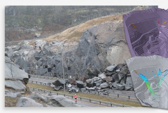
Rockfall Mitigation Project in West Virginia


Events
12th International Symposium on Field Monitoring in Geomechanics 2026

DFI 50th Anniversary Conference on Deep Foundations

9th International Symposium for Geotechnical Safety and Risk

5th International Symposium on Frontiers in Offshore Geotechnics (ISFOG)

Pan Mediterranean Geotechnical Engineering Conference

The Third Vietnam Symposium on Advances in Offshore Engineering

4th Asia-Pacific Conference on Physical Modelling in Geotechnics (ACPMG 2024)

The 2nd GeoMandu: Geotechnics for Sustainable Infrastructures

5th International Conference on Transportation Geotechnics


2 COMMENTS
Sally Simpson*
Apr, 05, 2013 Zhi and Tianshu,I like the review. There are a few typos that I would encourage you to edit. Also Figure 3 seems out of place.
Zhi Li
Apr, 08, 2013Exactly. This webpage is quite new to us. We are getting used to operate it. Thank you very much.
Edit Comment