Techniques for Geoenvironmental Characterization of Contaminated Sites
Introduction
Environmental contamination can occur from a number of sources due to historically bad practices and the growing needs of human civilization and industry. In the case of environmental contamination, site characterization is necessary, both to understand the type of contamination as well as the stratigraphy and hydrogeology of the subsurface. Example sources of contamination include landfills, underground storage tanks, and subsurface exploration techniques for energy production, such as fracking. Potential contaminants associated with site usage are suspended solids, nitrogen, ammonia, nitrates, and asbestos. Also included are heavy metals such as arsenic, cadmium, copper, lead, nickel, and mercury as a result of leachate. Due to water contamination, the site may contain petroleum hydrocarbons, phenols, polynuclear aromatic hydrocarbons (PAHs), and organophosphates [1]. Since soil conditions vary, and different types of contaminants require different methods of remediation, characterization of the geology, hydrogeology, type of contaminant, concentration, and distribution are vital in order to clean the site.
Contaminants may originate on the ground surface, in the vadose zone, or in the saturated zone, below the water table. Contaminants originating on the ground surface include the infiltration of contaminants to groundwater, leachate from Subtitle C and D landfills, disposal of sewage and water treatment sludges, and particulate matter from airborne sources. Contaminants from the vadose zone include those involved in waste disposal from prior excavations, waste from surface impoundments, and septic tanks or leaking underground storage tanks (LUSTs). Contaminants originating in the saturated zone include contaminants involved in waste disposal from wet excavations, mining tailings, agricultural drainage wells, and those involved in deep well injection for the disposal of hydrofracturing liquids.
Traditional methods to obtain site characterization data include invasive drilling and sampling, particularly auger-based drilling or rotary drilling with a bentonite slurry. Traditional methods of sampling include split-spoon sampling for cohesionless materials and thin-walled tube sampling for finer, cohesive soils. These are commonly used in conjunction with borehole sampling methods such as the standard penetration test (SPT) or a form of cone penetration testing (CPT), whether seismic or piezocone. Traditional sampling techniques for groundwater include the dissipation test for hydraulic conductivity, or a water monitoring well for hydrostatic level and ground and surface water samples.
Conventional sampling methods tend to be invasive and expensive operations, which require rig mobilization, drilling crews, carry high uncertainty, and run the risk of spreading contamination to other parts of the site [2]. Therefore, noninvasive methods have been developed for testing and sampling for characterization of contaminated sites. While conventional test methods are necessary and informative, they often do not adequately cover the contaminated site in its full spatial extent and best-guess mapping of the subsurface is necessary, which leads to sources of error in the remediation process [3]. Geophysical methods are well suited for characterization of large contaminated sites due to the ability of these methods to measure physical properties in a non-invasive, non-destructive, and near-continuous manner at a large scale that overlaps the small-scale, localized measurements performed with conventional testing [4].
Drilling Techniques
Currently, the most common practice of sampling contaminated sites requires drilling so that samples can be collected below the ground surface. These techniques usually involve borehole drilling and samples extracted at discrete depths below the surface and tested in the laboratory rather than on site.
Soil Gas Monitoring Well
Soil gas monitoring wells can be used to collect a representative sample of the soil gas to be collected at the sampling location while maintaining sufficient volume of soil gas for extraction and sufficient time for equilibrium of volatile organic compounds (VOCs). These wells are based on the theory of vapor intrusion where gas-phase VOCs migrate from subsurface soils or groundwater into the ground surface.
A schematic of a typical shallow soil gas monitoring well using granular backfill and PVC screening is presented in Figure 1.
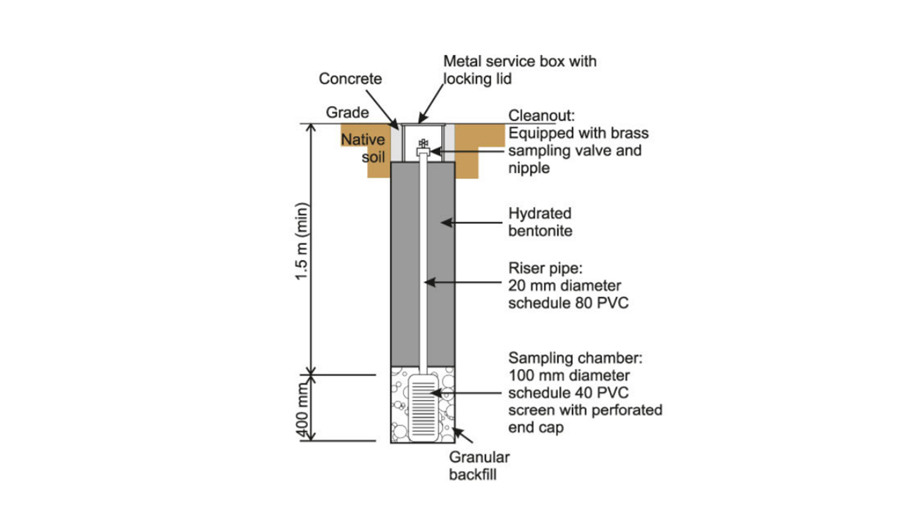
Figure 1. Schematic of a Typical Soil Gas Monitoring Well [5]
More direct sampling procedures include indoor air sampling or shallow soil gas sampling adjacent to the foundation from the vadose zone. Soil gas samples are typically collected from monitoring wells or soil gas probes using auger-drilled boreholes or push-in borings. Other methods involve soil gas extraction with the use of a vacuum pump or canister, and samples are analyzed in the laboratory. However, these methods are limited by factors such as high humidity, stagnant air, and extraction recovery [5].
Horizontal Soil Sampling
The majority of geoenvironmental and geotechnical site investigation procedures are performed using vertical drilling rather than horizontal drilling. However, vertical drilling is limited by several factors including lack of accessibility beneath structures, the requirement for numerous boreholes, and the possibility of contaminant migration through low permeability layers [6]. Horizontal directional drilling has been used by the petroleum industry extensively rather than vertical drilling because it overcomes these limitations and can be adapted for geotechnical use.
Horizontal directional drilling first drills the entire borehole, resurfacing at a target location using wet rotary drilling procedures. The drill head is then removed and replaced by a multiple-port sampler, which is pulled through the borehole, taking samples at designated locations. This differs from vertical drilling where the sample is collected ahead of the drilling head. A schematic of the multiple-port sampler is pesented in Figure 2.

Figure 2. Schematic of a Multiple-Port Horizontal Soil Sampler [6]
Drawbacks of horizontal directional drilling include the large size of the sampler, which limits the use of the tool. However, a smaller size sampler which could be used with medium- and small-sized drilling rigs is prone to possible contamination of the sample during retrieval and there is uncertainty in the location of sampling. Moreover, the sampling process is repetitive and lengthy and is therefore not cost effective [6].
This technique is most advantageous because it allows for borehole stretching over extensive horizontal distances, which makes it possible to sample beneath buildings or to remotely sample environmentally hazardous areas.
Displacement Method
In order to sample for groundwater contamination, the displacement method can be used with either column displacement, vacuum displacement, or immiscible displacement. Samples are taken of the soil solution, which is the liquid phase of soil in equilibrium with the solid phase. This contaminated soil solution is replaced with other fluids and then is transported to be tested ex-situ.
The displacement method is problematic in that there is the risk of possible contamination of the soil solution during the displacement step of the technique. Additionally, the use of immiscible liquids for displacement is problematic because they tend to be volatile and generally toxic [7].
Geophysical Techniques
Geophysical techniques have been used in the past to identify geological structures and these methods have been expanded to be used in contaminated site characterization. Methods such as ground-penetrating radar (GPR), electrical resistivity tomography (ERT), electromagnetic induction (EMI) surveys, and direct push sampling are less invasive and may allow for a more complete understanding of the contaminants and geometry of the site [3].
While geophysical testing does provide localization and characterization of the spatial extent of subsurface contaminant distribution, there is no direct detection of contaminants. This is due to the simultaneous presence of multiple signal sources from geological structures and hydrogeologic layers, which tend to overwhelm those from contaminant concentrations [3]. This leads to misidentification of the contaminant or failure to capture the contaminant location.
However, in the case of hydrocarbon contamination, biological activity associated with hydrocarbon degradation provides a strong electrical signal, allowing geophysical methods to be used with accuracy and repeatability. Furthermore, in the case of large sites such as reclaimed landfills, the large chemical and physical heterogeneity of the sites are difficult to characterize using traditional drilling and sampling methods [4].
Radon Monitoring
Radon monitoring, or emanometry, can be used to estimate the location, amount, and interfacial area of nonaqueous phase liquids (NAPLs) in the vadose and saturated zones. Monitoring of radon concentrations in soil gas can also be used to detect zones of differing permeability and the presence of fracture zones [8], which can act as conduits for contaminated materials.
Its use is based on the theory that hydrocarbons in the subsurface produce a reduction area surrounding their accumulation, which in turn causes uranyl ions dissolved in the groundwater to reduce from an oxidation state and precipitate around the hydrocarbon accumulation. Precipitated uranium forms around this hydrocarbon pool, later disintegrating into radon gas, which then migrates to the ground surface. Once at the ground surface, the radon can be registered as a signal marking the contour of the subsurface NAPL accumulation. Therefore, the reduction in radon activity in the soil air of the vadose zone indicates the presence of underlying levels with high hydrocarbon saturation [2]. Figure 3 details the variation of radon concentrations in the environment as well as its migration path to the surface.
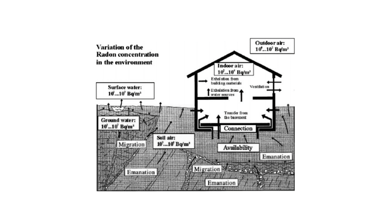
Figure 3. Radon Concentration Variability in the Subsurface [21]
Radon monitoring is advantageous in that it can be used to locate and determine the boundaries of free-phase plumes even in the case where the quantity of organic vapors reaching the surface is low to nonexistent [2]. Additionally, drilling and core-sampling, the traditional methods for locating and quantifying NAPLs, is expensive and requires invasive drilling for the installment of a sampling well. Most importantly, this method is not sensitive to changes in subsurface properties and can be used extensively for contaminants with low vapor pressure, unlike the traditional method where ex-situ sampling of contaminants with low vapor pressure is both time consuming and difficult. Additionally, if preliminary information such as the location of the source zone is lacking, then there is a significant risk of wasting time and capital in drilling and installing wells in the incorrect location, producing misleading data [2].
Typically, radon gas detection instruments are separated between passive methods with no power supply and analysis is performed after exposure, or active methods with an electrical power supply and direct data reading. Direct measurements collected in air either measure radon gas or its progeny. Measurements of radon gas require grab sampling and analysis in a laboratory. Measurements of radon progeny use a manifold composed of a compressor, pressure monitoring sensors, a data system, and a fore-pump, as shown in Figure 4 [21].

Figure 4. Schematic of Radon Measurement Manifold [21]
According to testing by Gonzalez et al (2008) at hydrocarbon storage and distribution centers in Spain, the radon monitoring method is repeatable and in-situ monitoring of radon concentrations is suitable to determine the surface trace of plume boundaries for site assessment and remediation.
However, this method is limited in relation to soil moisture. The influence of soil humidity is large enough to invalidate radon measurement for sampling conducted below the water table, regardless of the method of filtering of circulated soil air [2]. Additionally, the radon monitoring method is limited by time efficiency where measurements are more time consuming than direct soil gas measurements through drilling, but is useful where invasive sampling is not possible.
Ground Penetrating Radar (GPR)
Ground penetrating radar, or ground-probing radar (GPR) is a geophysical technique used to delineate differences in the subsurface stratigraphy. It can also be used extensively in hydrogeological investigations, using GPR responses to detect the absence or presence of water [10]. In this method, electromagnetic waves are propagated through the soil from the surface and disturbances to the signal delineate differences in stratigraphic layers. This method can be used to characterize differences in water content, soil fabric, and soil density, as stratigraphic information is crucial to understanding the scale of heterogeneity for hydraulic conductivity and porosity.
Figure 5 presents a typical GPR measurement system, including the controller, transmitter and receiver antennae, and data storage system [23].

Figure 5. Typical GPR Measurement System [23].
GPR is based on electromagnetic theory such as Maxwell’s equations for electromagnetic fields and constitutive relationships for quantifying material properties. The constitutive relations relate the material physical properties detected to the application of electromagnetic fields. GPR focuses on the wave propagation aspect of electromagnetic fields, particularly phase velocity, attenuation, and electromagnetic impedance. Interface boundaries are detected when a signal is reflected or scattered and both an incident wave and a reflected wave are produced. The presence or absence of water drives the signaling behavior, since pore water generally contains ions and electrical conductivity is measured based on ion mobility [10].
GPR methods use either reflection or transillumination, where a transmitter and receiver are configured at the surface so that subsurface reflectivity versus spatial position can be mapped [10]. Transillumination surveys are also available, but rely on the use of boreholes to perform measurements and thus lose the advantage of noninvasive testing.
Cassiani et al (2014) conducted tests to demonstrate the relationship between noninvasive tests and contamination on the Trecate, Italy site with hydrocarbon contamination. GPR methods, along with electromagnetic induction, direct push sampling, and soil electrical conductivity were used to match with past site characterization data in order to confirm the usefulness and validity of GPR measurements. The electrical resistivity profile as compared to the GPR subsurface profile is presented in Figure 6. In Figure 7, the high conductivity zone expected to contain hydrocarbon contamination formed from electrical conductivity and borehole testing is compared to that obtained through GPR testing. It was determined that GPR was useful and accurate in determining both spatial resolution and extent of hydrocarbon contamination [3].
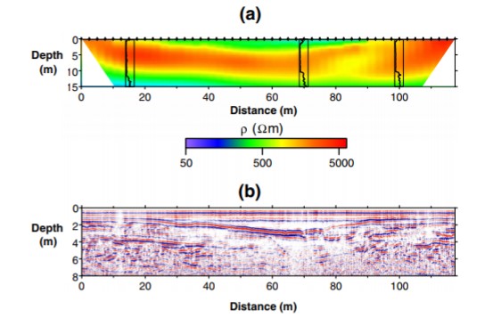
Figure 6. a) Subsurface profile obtained through resistivity imaging, b) subsurface profile obtained through GPR[3]
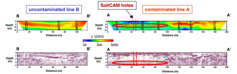
Figure 7. Expected hydrocarbon contamination derived from a) electrical resistivity testing, b) GPR testing[3]
Since GPR signals are sensitive to water content, the water table can be mapped without the use of a monitoring well or drilling. For groundwater contaminant detection, contaminants either dissolve or displace pore water, which GPR can detect from the surface [10]. A major benefit of GPR is its ability to monitor changes in pore chemistry quickly and without drilling, so there is no need for rig mobilization or sampling boreholes.
Drawbacks of GPR methods include the limitation in depth available to testing. For example, in the case of thick clay layers, the waves will be strongly attenuated, so an even shallower depth needs to be used for testing. Additionally, areas of saline groundwater can block GPR signal penetration. Therefore, testing is efficient only for coarse-grained materials which are transparent to radiowave signals and is site-specific in nature [10].
Bioattenuation
The bioattenuation method is a geophysical method used to detect and monitor hydrocarbon contamination. It is based on the theory that biological byproducts of hydrocarbon degradation produce electrical signals which can be interpreted at the ground surface. Excess organic matter from LNAPL contaminated sites catalyzes microbial activity, where microbes feed on hydrocarbons, altering hydraulic properties and the ionic composition of groundwater [22]. The byproducts of this phenomenon are oganic and carbonic acid, which weather the solid matrix, changing pore fluid chemistry and therefore electrical conductivity [3]. Methods such as radon monitoring or ground penetrating radar can be used to measure geophysical signals such as electrical resistivity or electromagnetic waves [22].
Figure 8 presents a schematic of an LNAPL-contaminated site in three cross-sections, with corresponding bulk electrical conductivity variations. By measring electrical conducitivity at a site and analyzing the changes in measured electrical conductivity due to hydrocarbon degradation, the profile of an LNAPL plume can be mapped for the subsurface [22].

Figure 8. Profile of LNAPL-Contaminated Site for LNAPL plume and bulk electrical conductivity. a) longitudinal cross-section b) vertical cross-section c) transverse cross-section [22]
This method is limited due to the reliance of the geophysical response on the type of contaminant. Therefore, electriccal conductivity measurents using bioattenuation methods are largely site-dependent and require case-specific analysis [3]. It is also limited in its reliance on other geophysical methods to collect and interpret data.
Electrical Resistivity Method
The electrical resistivity method is another geophysical technique used to determine subsurface stratigraphy as well as hydrogeological formations. It can particularly be used for determination of the spatial distribution of the low-frequency resistive and capacitive characteristics of the soil [11]. It can be used in landfills to measure the distribution of leachate, determine the area of contamination of leachate in surrounding soil and rock, monitor the migration of leachate, and characterize geologic and subsurface engineered structures [12].
For this method, electrodes are used to create an electrical circuit and a voltage is introduced into the soil as a current travels through the subsurface material to close the circuit. The potential difference between electrodes is measured and from this the apparent resistivity is determined [11]. The time it takes to close the circuit is indicative of the type of soil the current is traveling through, which helps to characterize the subsurface soils. A schematic of a typical electrical resistivity measurement system is presented in Figure 9.
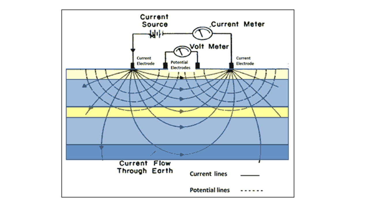
Figure 9. Schematic of Typical Electrical Resistivity Measurement System [24]
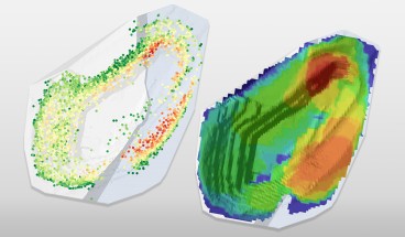
Feng et al. (2017), performed testing to detect leachate distribution at a bioreactor landfill in Laogang, China, using electrical resistivity tomography. They found that there is a direct correlation between electrical resistivity and volumetric moisture content. Additionally, this method was found to be a cost-effective, non-invasive, and rapid means of generating spatial models of the subsurface. The three-dimensional plot of spatial resistivity from testing is presented in Figure 10. Four cross sections were combined and converted to volumetric moisture content. Because the cross-sections match well when combined, the technique was considered to be accurate and reliable [12].
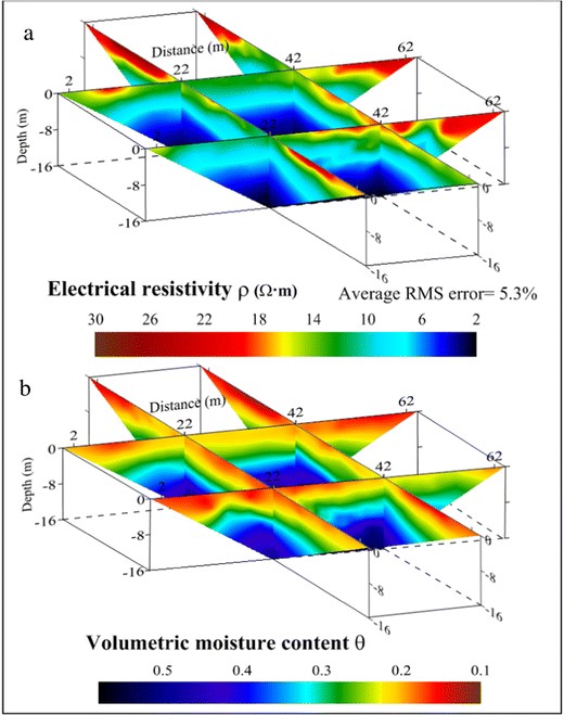
Figure 10. a) Electrial resistivity with spatial variation, b) Volumetric moisture content with spatial variation [12]
This method is beneficial because it is widely applicable to laboratory and field scales, is relatively easy to perform, requires no expensive equipment or rig mobilization, and uses readily available data processing tools. Additionally, the relationships between porosity, water content, and resistivity have been established and can be correlated from test results [11].
The DC resistivity method is limited in that testing in the saturated zone requires down-borehole testing, which eliminates the advantages of noninvasive testing. Furthermore, data collection is slow - particularly for three-dimensional investigations. The simulated data also has an inherently bad mass balance in characterization of solute transport due to reduced sensitivity with distance from electrodes [11]. However, the electrical resistivity tomography method was proven to be less time-consuming and demonstrated accuracy of results [12].
Electromagnetic Resistivity
Electromagnetic resistivity, or vertical induction, is a geophysical method to detect contaminants in the soil. This method employs an alternating current (AC) to measure secondary electromagnetic current, which can then be correlated to the resistivity of a material. This method is based on the theory that clays are more conductive than sands but less conductive than water. Similarly, contaminated water is more conductive than pure water, therefore contaminants in the soil can be detected based on the resistivity read on site.
Controlled-Source Electromagnetic Induction Method
Controlled-source electromagnetic induction (CSEM) method is another geophysical technique for hydrogeological characterization. It is advantageous because it is a surface method and requires no rig mobilization or invasive drilling and the instrumentation involved is relatively inexpensive and commercially available. Additionally, it performs well in conductive soils where GPR is difficult to perform or interpret [13]. This method also performs better in regions where the terrain dictates poor electrode contact with the ground, which is needed for DC methods [14].
Figure 11 presents a schematic of a typical CSEM system, with electrodes penetrating only the topsoil and electrodes above the ground surface.

Figure 11. Schematic of CSEM System. a) electrodes penetrating topsoil, b) electrodes above ground surface. [25]
This method is much faster than traditional, invasive testing. However, this method is limited by scale effects on hydraulic conductivity, as hydraulic conductivity measurements tend to increase with increasing measurement scale. This effect could incorrectly characterize the subsurface materials [13].
Complex Permittivity
Heavy metal contamination in the subsurface can be detected using complex permittivity measurement techniques. Complex permittivity is an intrinsic property which reflects the extent of polarization and conduction that the molecules of the material undergo when subjected to an electromagnetic field. It is dependent on the constituents of a material and is affected by factors such as pore water chemistry, soil water content, density, degree of saturation, and mineralogy. Since complex permittivity varies with soil pore-water chemistry, it can be used to characterize the soil-water system of a site. Furthermore, it can be used to create a database to analyze and map contaminants in the soil.
When subjected to an applied electromagnetic field, the complex permittivity reflects the physical and chemical properties of the material, and a change in pore-fluid chemistry will change the complex permittivity. Relative complex permittivity is composed of a real parameter, which reflects the polarizability of the material, and a complex parameter, which represents the energy loss due to polarization and ionic conduction. Since complex permittivity of soil-fluid mixtures is affected by water content, density, and the chemical composition of the pore fluid, changes in these characteristics may also change the soil fabric, double-layer formation, and conductivity of the pore fluid, all of which affect the dielectric polarization [15].
Shang and Rowe (2003) developed a permeation cell for testing of soil samples with known contamination in order to assess the potential for complex permittivity to be used for identifying contaminant migration at both municipal solid waste sites and industrial waste sites. They determined that the relative permittivities of soil specimens were highly consistent, indicating that the permittivity measurement is repeatable and reliable [16]. The complex permittivity of the soil samples before permeation is presented in Figure 12. This suggests that the soil pore fluid dominates the complex permittivity of the soil mass, which makes complex permittivity a reliable indicator of pore fluid chemistry [16].
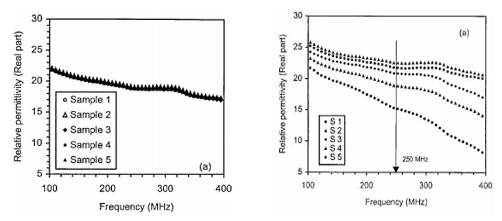
Figure 12. Complex permittivity of soil samples a) before permeation and b) after permeation [16]
This method is more efficient than current methods that require on-site sampling and laboratory chemical analysis, which are expensive. While one alternative approach for groundwater monitoring is to use electromagnetic waves for routine monitoring, the field apparatus is expensive [15]. Additionally, conventional methods of field testing are unable to measure results in real time and are destructive in nature, as well as expensive and time consuming. The complex permittivity measurement used in conjunction with complex neural networks allow for characterization of subsurface contamination while being noninvasive and relatively fast [17].
However, one disadvantage of this method is that it is temperature dependent, meaning permittivity will increase with an increase in temperature. Fortunately, this can be remedied through temperature calibration during data analysis [15].
Lysimetry
Lysimetry is a low-invasive soil solution sampling technique which allows for obtaining the soil solution with less destruction of the soil structure. It also allows for continuous sampling within the same location. Lysimetry techniques include tension cup lysimeters, zero-tension lysimeters, and passive capillary samplers [7].
It is necessary to monitor the soil solution, particularly for fate and transport of environmentally consequential pollutants. In fact, soil solution sampling techniques for effectively monitoring the quality and quantity of vadose zone pore water can be used to assess the location and transport of potential groundwater pollutants as well as to develop appropriate remediation strategies. Accurate sampling of soil solutions and their analyses determine the potential location and mobility of groundwater pollutants [7].
A tension cup lysimeter consists of a porous ceramic cylinder attached to a PVC pipe projected above the ground. Suction is applied to an attached neoprene tube and the soil solution sample is collected from the other tube. Applied tension allows the sample to be drawn into the cup, through the tubing, and into the sample collection chamber. This method relies on gravitation and matrix potential gradients via suction on the porous surface. Drawbacks to this method are that tension cup lysimeters are subject to damage due to microbial activity. Microbes tend to colonize in the cups and may clog pores with biofilms that sorb biotransformable chemicals [7].
A schematic of the installation methods of a tension-cup lysimeter is presented in Figure 13. Lysimeters can be installed horizontally, shaftless, at a 45 degree angle, or vertically [7].
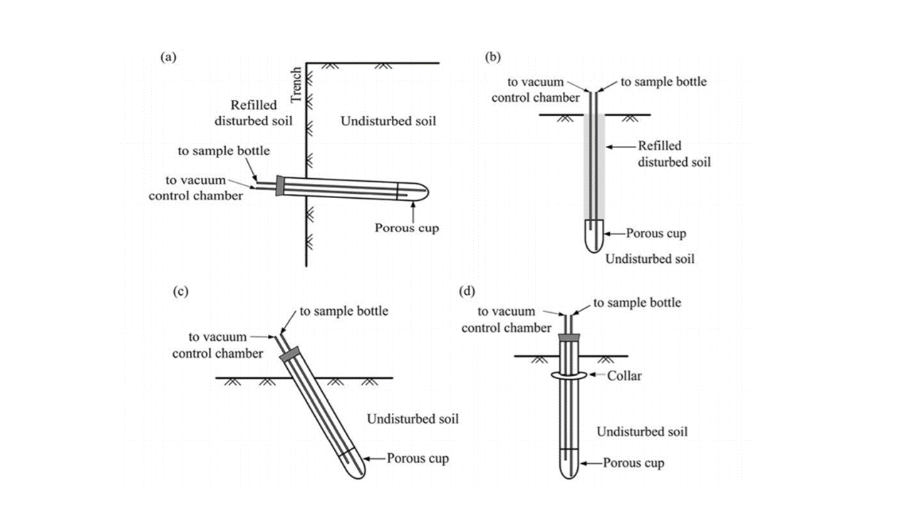
FIGURE 13. Schematic of Lysimeter Installation. a) Vertical installation b) Shaftless installation c) Angled installation d) Vertical installation. [7]
The zero-tension lysimeter, like the tension cup lysimeter, relies on gravitational force to operate. However, the zero-tension lysimeter uses the gravitational force to cause water to move through the porous plate surface of the lysimeter and uses a saturated soil zone above the porous surface to sample a clear fraction of the soil solution. Unlike the tension cup lysimeter, the zero-tension method can be used to sample saturated flow, whereas the tension cup method more efficiently samples unsaturated flow within soil aggregates [7]. The zero-tension lysimeter is limited in that it significantly undersamples vadose soil water. However, due to the porous plate surface used there is no risk of contamination of the soil solution.
The passive capillary sampler is similar to the tension cup lysimeter, but it uses fiberglass wicks to produce a hanging water column which exerts tension on the soil solution above the lysimeter and the collected sample is transported along the wick into a container. This method is advantageous because samples can be collected in both saturated and unsaturated conditions and tensions can be designed to match that of the soils being sampled [7], so there is no limitation on the type of material this method can be used with.
Apparent Electrical Conductivity
Spatio-temporal changes in soil quality can be monitored using apparent electrical conductivity for modeling of solute transport in the vadose zone. This type of geophysical technique is preferable because of the possibility of contaminant transport due to conventional sampling. The spatial variability of soil physical and chemical properties is significant to the mitigation of environmental contaminants because it affects subsurface solute transport.
Figure 14 shows a typical mobile soil electrical conductivity sensor. This device can measure topsoil data, weighted depth readings, and deep soil data [18].
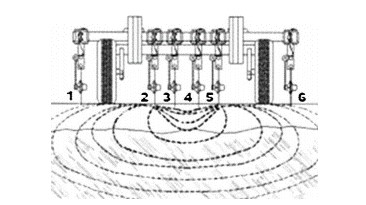
Figure 14. Typical mobile electrical conductivity sensor [20]
Because of the pathways of conductance, electrical conductivity is influenced by interaction of soil properties including salinity, percent saturation, water content, and bulk density. Both percent saturation and bulk density are influenced by clay content and organic matter. Since the exchange surfaces on clays and organic matter provide a soil-liquid phase pathway via cation exchange, clay type and content, cation exchange capacity (CEC), and organic matter also influence the measurement of electrical conductivity [19]. Due to the influence of these properties on conductivity, the spatial distribution within a site provides the means of mapping the variability of these properties. Additionally, the stratigraphy of the subsurface can be determined through apparent electrical conductivity measurements because smaller soil grains such as clays conduct more current than larger grained particles like silts and sands [18].
Moral et al. (2010) conducted experiments using apparent electrical conductivity measurements in order to determine spatial distribution for a site. They found high positive correlation of conductivity with fines and negative correlation with coarse material, indicating that correlations of electrical conductivity with soil texture is an effective method to determine subsurface stratigraphy [18]. The results of the testing, for apparent conductivity with depth for different soil textures is presented in Figure 15.
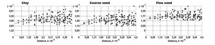
Figure 15. Apparent electrical conductivity with depth for various soil textures [18]
Apparent soil electrical conductivity measurements are preferable because they can be performed in-situ and are reliable. The equipment is easy to mobilize and is cost-effective. Furthermore, measurement of apparent soil electrical conductivity can provide spatial information for optimization of soil sampling as well as characterization of soil properties and can be used across a wide range of soils [18].
This method is limited in that modeling of relationship between apparent electrical conductivity and soil variables is difficult since many soil properties are dependent on electrical conductivity and requires secondary sources of information [18].
Conclusion
Due to the inherent uncertainty in subsurface exploration and sampling, drilling and sampling methods which can overcome uncertainty are necessary. Because traditional methods of drilling and sampling carry the possibility of contaminant spread, low-invasive to non-invasive methods can better characterize subsurface stratigraphy and detect the extent of contaminated plumes without spreading contamination. Geophysical methods such as radon monitoring, bioattenuation, ground penetrating radar (GPR), lysimetry, complex permittivity, and apparent electrical conductivity are viable methods for this end.
References
References
[1] Environmental Resources Management Australia, Landfill Thin Guide for Environmental Officers, 2004
[2] Garcia-Gonzalez, J.E., Ortega, M.F., Chacon, E., Mazadiego, L.F., De Miguel, E. “Field Validation of Radon Monitoring as a Screening Methodology for NAPL-Contaminated Sites,” Applied Geochemistry, Vol 23, No. 9, 2008.
[3] Cassiani, C., Binley, A., Kemna, A., Wehrer, M., Orozco, A.F., Deiana, R., Boaga, J., Rossi, M., Dietrich, P., Werban, U., Zshornack, L., Godio, A, JafarGandomi, A., Deidda, G.P., “Noninvasive Characterization of the Trecate (Italy) Crude-Oil Contaminated Site: Links Between Contamination and Geophysical Signals,” New Approaches for Low-Invasive Contaminated Site Characterization, Monitoring and Modeling, 2014.
[4] Boudrealt, J., Dube, J., Couteau, M., Winiarski, T., Hardy, E., “Geophysical Characterization of Contaminated Urban Fills,” Engineering Geology, Vol 116, 2010.
[5] Wong, T.T., Agaar, J.G., “Development of a Technically Defensible Soil Gas Sampling Strategy for Vapour Intrusion Assessments,” Canadian Geotechnical Journal, Vol 46, 2009.
[6] Ariaratnam, S.T., Allouche, F.N., Biggar, K.W., “Testing of a New Generation Horizontal Soil Sampler,” Canadian Geotechnical Journal, Vol 37, 2000.
[7] Fares, A., Deb, S.K., Fares, S., “Review of Vadose Zone Soil Solution Sampling Techniques,” Enviornmental Reviews, Vol 17, 2009.
[8] Reddy, D.V., Sukhija, B.S., Nagabhushanam, P., Reddy, G.K., Kumar, D., Lachassagne, P., “Soil Gas Radon Emanometry: A Tool for Delineation of Fractures for Groundwater in Granitic Terrains,” Journal of Hydrology, Vol 329, 2006.
[9] Porowska, D., “Identification of Groundwater Contamination Zone around a Reclaimed Landfill Using Carbon Isotopes,” Water Science & Technology, Vol 75, No 2, 2017.
[10] Rubin, Y., Hubbard, S.S., “GPR Methods for Hydrogeological Studies”, Hydrogeophysics, 2005.
[11] Binley, A., Kemna, A., “DC Resistivity and Induced Polarization Methods,” Hydrogeophysics, 2005.
[12] Feng, S., Bai, Z., Cao, B., Lu, S., Ai, S., “The Use of Electrical Resistivity Tomography and Borehole to Characterize Leachate Distribution in Laogang Landfill, China,” Environmental Science and Pollution Research, Vol 24, No 25, 2017.
[13] Everett, M.E., Meju, M.A., “Near-Surface Controlled-Source Electromagnetic Induction: Background and Recent Advances,” Hydrogeophysics, 2005.
[14] Hesthammer, J., Svein, E., Boulaena, M., Rosten, T., Eidesmo, T., “Electromagnetic Imaging in Search for Hydrocarbons,” Marine and Petroleum Geology, 2005.
[15] Rowe, R.K., Shang, J.Q., Xie, Y., “Complex Permittivity Measurement System for Detecting Soil Contamination,” Canadian Geotechnical Journal, Vol 38, 2001.
[16] Shang, J.Q., Rowe, R.K., “Detecting Landfill Leachate Contamination Using Soil Electrical Properties,” Practice Periodical of Hazardous, Toxic, and Radioactive Waste Management, 2003.
[17] Amagashie, F., Shang, J.Q., Yanful, E.K., Ding, W., Al-Martini, S., “Using Complex Permittivity and Artificial Neural Networks to Identify and Classify Copper, Zinc, and Lead Contamination in Soil,” Canadian Geotechnical Journal, Vol 43, Iss1, 2006.
[18] Moral, F.J., Terron, J.M., Marques da Silva, J.R., “Delineation of Management Zones Using Mobile Measurements of Soil Apparent Electrical Conductivity and Multivariate Geostatistical Techniques,” Soil and Tillage Research, Vol 106, No 2, 2010.
[19] Corwin, D.L., Lesch, S.M., Oster, J.D., Kaffka, S.R., “Monitoring Management-Induced Spatio-Temporal Changes in Soil Quality Through Soil Sampling Directed by Apparent Electrical Conductivity,” Geoderma, Vol 131, 2006.
[20] Mohammadadeh, H., Clark, I., “Bioattenuation in Groundwater Impacted by Landfill Leachate Traced with δ13C,” Groundwater, Vol 49, 2011.
[21] Baskaran, M., "Radon Measurement Techniques," Radon: A Tracer for Geological, Geophysical and Geochemical Studies, 2016.
[22] Atekwana, E.A., Atekwana, E.A., "Geophysical Signatures of Microbial Activity at Hydrocarbon Contaminated Sites: A Review," Surveys in Geophysics, Vol 31, 2010.
[23] Utsi, E.C. "Fundamentals of GPR Operation," Ground Penetrating Radar: Theory and Practice, 2017.
[24] Chandra, P. "Electrical Resistivity Methods," [Online].
[25] "Land Based Controlled Source Electromagnetic Exploration" GFZ German Research Centre for Geosciences. [Online].
 Daiyue Jin
  Michelle Basham
 Industry News


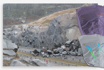
Rockfall Mitigation Project in West Virginia


Events

12th International Symposium on Field Monitoring in Geomechanics 2026

DFI 50th Anniversary Conference on Deep Foundations

9th International Symposium for Geotechnical Safety and Risk

5th International Symposium on Frontiers in Offshore Geotechnics (ISFOG)

Pan Mediterranean Geotechnical Engineering Conference

The Third Vietnam Symposium on Advances in Offshore Engineering

4th Asia-Pacific Conference on Physical Modelling in Geotechnics (ACPMG 2024)

The 2nd GeoMandu: Geotechnics for Sustainable Infrastructures

5th International Conference on Transportation Geotechnics


4 COMMENTS
Eva*
Dec, 05, 2017 This is a complete citation of sampling techniques for contaminated sites' characterization, with lots of scientific sources. Very important that you mention the pros and cons of each of them! Michelle Basham
Dec, 18, 2017 Eva,Thank you for taking time to review our class project and offer comments. We value your input and have added pros and cons for each method.
Thank you,
Michelle and Daiyue
Edit Comment
Sally Simpson*
Dec, 13, 2017 Thank you for a nice overview of the various site characterization techniques. I think the report would be even better if it had pictures of the various techniques. I would be particularly interested in seeing what the radon monitoring equipment looks like. If you can add that, this would be great! Michelle Basham
Dec, 18, 2017 Sally Simpson,Thank you for taking the time to review this project. We agree that the techniques need figures to better explain their utility and have updated the content accordingly, particularly for radon monitoring equipment.
Again, we appreciate the time you spent reviewing this.
Thank you,
Michelle and Daiyue
Edit Comment