Unconfined Compression Test
Contents [show]
The Unconfined Compression Test is a laboratory test used to derive the Unconfirmed Compressive Strength (UCS) of a rock specimen. Unconfirmed Compressive Strength (UCS) stands for the maximum axial compressive stress that a specimen can bear under zero confining stress. Due to the fact that stress is applied along the longitudinal axis, the Unconfined Compression Test is also known as Uniaxial Compression Test. UCS is a parameter widely used in geotechnical design, but may not represent the strength in-situ. On a large scale, the rockmass properties are highly affected by other factors including discontinuities, faults and weathering.
During the test, apart from the axial load, axial and lateral deformation are commonly measured to derive the sample’s elastic modulus and Poisson’s ratio.
Laboratory Procedure
Sampling
Samples are retrieved by drill cores and are selected cautiously in order be representative of the original rock formation. The minimum diameter of a specimen must be at least 47 millimeters and 10 times larger than the size of the largest mineral grain (or 6 times larger for weaker rocks e.g. sandstones, marlstones).
The samples’ length to diameter ratio (L/D) must be between 2.0 and 2.5, according to ASTM (American Society for Testing and Materials) and 2.5-3.0 according to ISRM (International Society for Rock Mechanics). The cylindrical surfaces are prepared in order to be flat and smooth. In particular, the sample’s ends must be leveled within a 0.02 millimeters tolerance and they should not depart from perpendicularity by more than 0.06 degrees.
The purpose of the procedure is to preserve the in-situ properties of the sample until the test is conducted. Therefore, moisture recorded in the field should also be preserved until testing.
At least 5 samples are required to achieve a reliable value of the UCS.
Apparatus
The apparatus used to conduct the Unconfined Compression Test consists of the following parts:
Loading Device: The loading device must be designed to consistently apply load at the required rate until the end of the test. The test may be stress- or strain-controlled. It is pointed out that only strain-controlled devices can capture the post-failure behavior of a material.
Platens: The axial stress applied by the loading device is transferred to the specimen by two steel platens that are made with a minimum Rockwell Hardness of 58. Their diameter must be at least equal to the sample’s diameter. The length to diameter ratio must also be at least 0.5.
Strain measurement devices: The axial and lateral deformations are measured by various devices (e.g. Linear Variable Differential Transformers (LVDTs), Compressometers, Electrical Resistance Strain Gages).
Testing Procedure
The two plates shall be carefully cleaned before the specimen is placed in the testing chamber. The load should be continuously applied at a rate of 0.5 MPa/s to 1.0 MPa/s (in case of a stress-controlled load device) and failure must occur in approximately 10 minutes. Stress and deformation data can be recorded through an electronic system that has the appropriate accuracy specifications. The maximum load is recorded in Newtons within a 1% accuracy.
Results
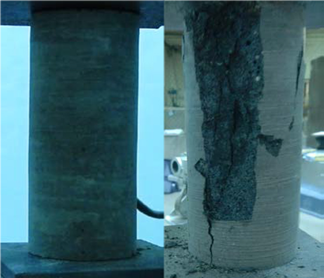
A typical stress-strain diagram deriving from a Uniaxial Compression Test of an undisturbed specimen of basalt is presented in Figure 1. The UCS is the peak value of the diagram and is equal to 44.7 MPa. Photos of the specimen before and after the test are presented in Figure 2. During the failure process, cracks propagated from the bottom to the top of the specimen, shearing off a large piece of the sample.

Figure 1: Stress-strain curve of the Unconfined Compression Test for a specimen of Basalt.

Figure 2: Photographs of the specimen before and after the testing procedure.
A recorded testing process of another basalt specimen is presented in the video below.
Calculations
The axial strain is calculated as:
εa = Δl / L0
Where εa: Axial strain, Δl: Change in measured axial length and L0: The initial length of the sample.
The diametric strain is calculated as:
εd = Δd / D0
Where εd: Diametric strain, Δd: Change in diameter and D0: The initial diameter of the sample.
The compressive stress is calculated as:
σ = P / A0
Where σ: Compressive Stress, P: Load and A0: The initial cross-section area of the specimen.
Therefore, the Unconfined Compressive Strength is calculated for the maximum load applied:
σUCS = Pmax / A0
The modulus of elasticity (Young's modulus) E which represents the ratio between axial stress and axial strain can be derived via several methods. Usually, it is calculated at stress-strain level of about 50% of the maximum load.
E = Δσ / Δεa (At 50% of maximum load)
The Poisson’s ratio that represents the ratio between diametric and axial strain, is calculated as:
n = - (εd / εa)
Size corrections:
According to ASTM, the preferable sample L/D ratio is 2.0. Therefore, a correction formula is applied for larger ratios (smaller rations are unacceptable). In particular, the Uniaxial Compressive Strength is re-calculated as:
σc = σUCS / (0.88 + 0.222*(D/L) )
Where σc is the corrected uniaxial compressive strength.
Rock characterization and typical range of UCS based on rock types
Based on their Uniaxial Compressive Strength, rocks can be characterized from very weak to very strong as following:
| Strength classification | Strength range (MPa) | Typical rock types |
| Very weak | 10-20 | weathered and weakly-compacted sedimentary rocks |
| Weak | 20-40 | weakly-cemented sedimentary rocks, schists |
| Medium | 40-80 | competent sedimentary rocks; some low-density coarse-grained igneous rocks |
| Strong | 80-160 | competent igneous rocks; some metamorphic rocks and fine-grained sandstones |
Table 1: Classification of rock hardnesses (from Attewell & Farmer 1976).
The range of the Uniaxial Compressive Strength for a large amount of typical rock types is presented in Table 2.
| Typical Rock Types | Uniaxial Compressive Strength (MPa) |
| Granite | 100-250 |
| Diorite | 150-300 |
| 100-350 | |
| Gabbro | 150-300 |
| 100-300 | |
| Gneiss | 50-200 |
| Marble | 100-250 |
| 100-200 | |
| Quartzite | 150-300 |
| Sandstone | 20-170 |
| Shale | 5-100 |
| 30-250 | |
| Dolomite | 30-250 |
Table 2: Typical values of Uniaxial Compressive Strength for a various number of rocks (from Attewell & Farmer 1976).
References
ASTM D7012-14e1, (2014). Standard Test Methods for Compressive Strength and Elastic Moduli of Intact Rock Core Specimens under Varying States of Stress and Temperatures, ASTM International, West Conshohocken, PA.
Attewell, P.B. and Farmer, I.W. (1976). Principles of engineering geology. Chapman and Hall, London.
ISRM, (1979). Suggested Methods for Determining the Uniaxial Compressive Strength and Deformability of Rock Materials. International Journal of Rock Mechanics and Mining Sciences & Geomechanics Abstracts. 16, 2.
Equipment Providers
Looking for Inclinometer Equipment? Fill in the form and we will contact them for you.
Media
- D. Zekkos Research Group
- D. Zekkos Research Group
Want to read more like this?
Triaxial Compression Test in Rock
Jun, 11, 2020 | EducationIntroduction Triaxial tests are widely used in geotechnical engineering both in soil and rock mec...

Point Load Test
Aug, 10, 2020 | EducationIntroduction Point Load (PL) is a test that aims at characterizing rock materials in terms of s...

Splitting Tensile Strength Test (Brazilian)
Aug, 10, 2020 | EducationIntroduction The Brazilian Test is a laboratory test conducted in rock mechanics to indirec...
Hoek-Brown Model – Rock Behaviour
Jun, 30, 2025 | EducationThe Hoek–Brown model is one of the most widely adopted constitutive models for simulating rock mass...
Laboratory Testing
Apr, 21, 2020 | EducationLaboratory testing is an integral part of geotechnical engineering research and practice. A well...

Direct Shear Test
May, 28, 2020 | EducationIntroduction The Direct Shear Test is an experimental procedure conducted in geotechnical engi...
Principal Considerations in Rock Engineering Practice and Contributions from Africa
Nov, 10, 2022 | NewsIn the Introduction to this paper, many names are mentioned of those with African origins or associ...

Soil Consolidation and Oedometer Test
May, 07, 2020 | EducationWhat is Soil Consolidation? Soil Consolidation refers to the process in which the volume of a satu...
Triaxial Test
Jun, 20, 2024 | EducationTriaxial Testing Soil triaxial testing is a fundamental procedure in geotechnical engineering...
Looking for Inclinometer Equipment? Fill in the form and we will contact them for you.
GET A QUOTE NOWOn This Day
July 12th 1850
READ MORE
Trending
Cohesion of Soil

Water Content (w)

Horizontal Soil Subgrade Reaction in Pile Foundations

Soil Subgrade Reaction

Slope Stability: The Janbu Method
The Hardening Soil Model

2.1. Normal and Shear Stress
