Prefabricated Vertical Drains
Contents [show]
Introduction
Prefabricated Vertical Drains (PVDs) or ‘Wick Drains' are composed of a plastic core encased by a geotextile for the purpose of expediting consolidation of slow draining soils. They are typically coupled with surcharging to expedite preconstruction soil consolidation. Surcharging means to pre-load soft soils by applying a temporary load to the ground that exerts stress of usually equivalent or greater magnitude than the anticipated design stresses. The surcharge will increase pore water pressures initially, but with time the water will drain away and the soil voids will compress. These prefabricated wick drains are used to shorten pore water travel distance, reducing the preloading time. The intent is to accelerate primary settlement. Pore water will flow laterally to the nearest drain, as opposed to vertical flow to an underlying or overlying drainage layer. The drain flow is a result from the pressures generated in the pore water. Figure 2 below demonstrate vertical water flow without the use of prefabricated wick drains, and horizontal water flow with the use of wick drains.

[B] Cross-Section With and Without Vertical Drains
Initial settlements are seldom of much practical concern, except for loads on thick plastic or organic soils having marginal stability wherein large shear deformation may continue due to undrained creep [6].
Prefabricated wick drains have several other purposes. They may be applied to reduce potential down drag on piles, or increase storage capacity for future landfills and waste containment sites. A developing application for PVD are the collection and extraction of contaminated groundwater, which may be coupled with cutoff walls to ensure full withdrawal.
History
In the 1920s, a technique for installing sand drains, a PVD predecessor, was patented in the U.S. The California Division of Highways, Materials and Research Department conducted laboratory and field tests on vertical sand drain performance beginning in 1933. Within the decade Walter Kjellman, then Director of the Swedish Geotechnical Institute, developed a prefabricated band-shaped vertical drain made of cardboard core and paper filter jacket which was installed into the ground with mechanical equipment [9]. Cardboard wick drains, and subsequently paper-wrapped plastic drains, were installed outside of the U.S. though the 1970s. A decade after that, entirely plastic PVDs were introduced as a more durable, reliable, and inexpensive option over the sand drains. Because these plastic drains could be installed very quickly as compared to sand drains, by the late 1980s, they largely replaced sand drains [17].
A case study for the acceleration of primary consolidation using wick drains is used to show some numbers on the time required for consolidation with and without the wick drains.
Construction of the New Istana (Royal Palace) for the Sultan of Brunei was to be completed before Brunei became independent in July 1983. This construction required fill to be placed on very soft compressible floodplain soils. Computations made before the fill placement in 1981 predicted several feet of fill settlement would occur from the consolidation beneath the floodplain area. The predicted primary consolidation settlement was 8.3 feet. For the 60 foot thickness of compressible soil, 50% of the settlement was estimated to take 3 years to complete, and 90% of the settlement was estimated to take 13 years. These predicted consolidations were computed by the method outlined by Leonards (1962). This required time frame was unacceptable and needed to be accelerated so that 90% of the consolidation settlement is completed within 6 months. A viable course of action was to install wick drains on the site.
A center to center spacing for the wick drains of 5 feet was computed by the method outlined in Hansbo (1979), based on the requirement that 90% consolidation of the soft sediments occur within the above mentioned 6 months. One foot of fill was placed every 2 days so that there were 85 1-foot increments in 6 months. The use of wick drains indicated that primary consolidation settlement would be accelerated by a factor of about 25, and the secondary compression to not be affected. There were 12 feet of fill placed before installation of the wick drains, and a subsequent 1.5 foot thick drainage blanket placed on top of the fill. Fill placement started in mid-September 1981 and was completed by the end of March 1982.
Surface settlement markers and deep settlement gauges were installed throughout the floodplain to provide settlement data before, during, and after the fill embankment construction, enabling ongoing evaluations of the wick drain performance. Early readings observed an immediate response to the installation of the wick drains. The last reading was taken in July of 1982 and the maximum settlement occurred was 7 feet. It was assumed this represented 90% of the primary consolidation and that total primary consolidation settlement would be 7.8 feet. This was in good agreement with the predicted maximum primary consolidation of 8.3 feet.
The installation of wick drains in the soft floodplain soils allowed construction of the fill embankment to proceed on schedule and brought about the desired results, increasing rate of consolidation by a factor of 25.
Drain Features
PVDs have a channeled or studded plastic core wrapped with a geotextile. The plastic core functions as support for the filter fabric, and provides longitudinal flow paths along the drain length. It also provides resistance to longitudinal stretching as well as buckling of the drain. The drain jacket acts as a filter to limit the passage of fine grained soil into the core area. It also functions to prevent closure of the internal water flow paths under lateral soil pressure.
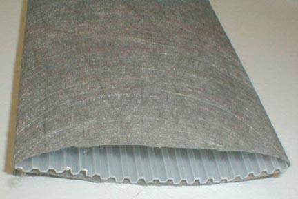
[C] Layfield Wick Drain Example

[D] Geosupply Wick Drain Example
Light-weight drains have a width to thickness ratio of 30-35. It is desirable for the surface area, which will permit seepage into the drain, to be 0.2-0.3 in2 (150-200 mm2) per 0.4 in (1 mm) length. The wick drains should be installed with a center to center spacing of 3 to 8 ft [17]. This will be discussed more in the design parameters section.
Equivalent Diameter
Wick drains have an oblong shape, but the available theories of radial consolidation have been derived for drains having a circular shape, often taken as equal to the nominal diameter of the sand drain. Fellenius (1977) suggested that the equivalent cylindrical diameter of a sand drain is the nominal diameter of the sand drain multiplied by the porosity of the sand in the drain [2]. The porosity of loose, free-draining sand can range from 0.4 to 0.5. This would result an equivalent cylindrical diameter of a sand drain of approximately half of the nominal diameter. In order to apply these theories to the design of field installations of wick drains, the equivalent diameter of an oblong shape is needed. Many equations have been suggested for computing the equivalent diameter, but each computation yields different results because they were derived under different assumptions.
The equations predicting the progress of consolidation around vertical drains assume a circular cross section for both the drain itself and the area the drain influences (Barron 1948).
Common wick drains have a plastic core surrounded by a geotextile:

[E] Cross-Section of PVD
Hansbo (1979) used a finite-element analysis and reported that the equivalent diameter of a drain is given as:
dw = 2 * ((b + t) / π) (1)
Where:
dw = equivalent diameter of the drain
b = width of the prefabricated drain
t = drain thickness
Rixner et al. (1986) suggests the following few equations:
dw = (b + t) / 2 (2)
dw = [(4*(b*t))/π]0.5 (3)
dw = 2(b'+ t') / π (4)
dw = [(4*(b'*t'))/π]0.5 (4)
Where:
2(b`+ t`) is used for free or open drain circumference
b`* t` is used for free or open drain cross section
b` and t` are reduced dimensions to account for clogging of the drain surface
In an independent evaluation by Richard P. Long and Alvaro Covo (1994), an electrical analog is used to define an equivalent diameter via evaluation of the previously listed equations’ varying results. A Sunshine Analog Field Plotter and electrically conducting paper were used. This technique uses the analogies of electrical potential to hydraulic head and electrical current to flow of water [14].
The procedure is represented as steady-state water flow for a model of ¼ of the drain cross section. A quarter of the cross section is used to eliminate repetition since the drain has two axes of symmetry. The model, seen below, is not applicable in the immediate vicinity of the drain at short times after consolidation begins. When water flows through a circular drain, rather than the supposed oblong profile, a shape factor for the flow net should be used [18].

[F] Flow Net for Flow to Oblong Drain from Circular Source
Shape Factor = Nf / Nd = 2 * π * ln(Re / Rw) (6)
Re = outside radius of the area
Rw = radius of central well
Nf = number of flow paths
Nd = number of head drops
Re, b, and t were varied throughout the Foott & Ladd (1981) study, and for each combination of values, a flow net was constructed using an analog field plotter. Using the shape factor and a summarization of the field plotter results, an equivalent diameter was determined.
dw = 2 * Rw
The results of the analog modeling are plotted below. The ratio of the computed equivalent diameter of the drain, dw, to the width, b, is plotted as the vertical axis and the ratio of the thickness of the drain, t, to width of drain, b, is plotted as the horizontal axis. The ratio of the thickness to width, t/b, in the analog model varied from 0 to 1.0, which includes all possible combinations of drain thickness and width. The results are represented by using an x and a straight line of least squares fit is shown.

[G] Plot of Equivalent-Drain-Diameter to Width-of-Drain Ration, d/b versus Thickness-of-Drain to Width-of-Drain Ration, t/v
Also on Fig. 3 are circles representing Suits et al. (1986) results from an experimental evaluation of equivalent diameters of drains.
Suits et al. method requires determining the coefficient of consolidation for remolded soil samples by standard laboratory tests, then consolidating the same soils using wick drains. The soils used for this experiment include, but are not limited to clay, organic silty clay, and peat. The reported values are approximately equal to the prediction from the linear least squares model [16].
Assuming negligible resistance to water flow, a unique value for dw, based on the model data for drain thickness and width, may be calculated. Equation (7) indicates that for t = b, dw = 1.2b, approximately the diameter of a circle with area b2. Equation (7) yields an appropriate value of the equivalent diameter of the drain for all t/b.
dw = 0.5 * b + 0.7 * t (7)
Values calculated from equations (1), (2), (3), and (7), and are combined with average experimental values from Suits et al. (1986) are shown in Table 1. The NYLEX and AMER-DRAIN were tested with clay only, but all over drain types were tested with each soil. Equations (2) and (7) report values similar to the experimental values. Whereas equation (1) values are consistently larger, and equation (3) values are smaller. Equations (2) and (7) seem to yield regularly agreeable values, however when b = t, the two methods yield results that vary by 20% [10].

[H] Comparison of Equivalent Drain Diameters by Various Methods
In summary, the equivalent diameter is essential for proper interpretation of field data to assess field conditions. The equivalent diameter of the shape of prefabricated drains was determined using an electrical analog field plotter. Values determined by this method agree with experimental values of Suits et al. (1986). Equivalent diameters of presently available prefabricated drains can be computed with reasonable accuracy from either equation (2) or (7), but (7) yields a more accurate value for all t/b.
Advantages and Disadvantages of Wick Drains
Advantages
- Decrease overall time required for completion of primary consolidation due to preloading
- Decrease the amount of surcharge required to achieve the desired amount of precompression in the given time
- Increase the rate of strength gain due to consolidation of soft soils when stability is of concern
- Comparison to sand drains:
- Economic competitiveness, less disturbance to the soil mass compared to displacement sand drains, and the speed and simplicity of installation. Also feasible to be installed in a nonvertical orientation. [12]
Rixner, Kraemer, and Smith (1986) have also outlined some technical advantages of PV drains compared to sand drains. They separate these advantages by sand drain type. There is displacement drains, which displace the soil as the drain is installed, and non-displacement, which does not displace the soil during drain installation. They found the following advantages of PVDs:
Displacement
- considerably less disturbance of cohesive soils during installation due to: smaller physical displacement by mandrel and top, and typically static push rather than driving
- installation equipment usually lighter, more maneuverable on site
- do not require abundant source of water for jetting
Non-Displacement
- do not require control, processing and disposal of jetted spoil materials; fewer environmental control problems
- field control and inspection not as critical
- definite potential for cost economy
- eliminate cost of sand backfill of drains, quality control problems and related truck traffic
- jon control and inspection requirements are reduced due to simplification of installation procedures
General
- there is greater assurance of a permanent, continuous vertical drainage path; no discontinuities due to installation problems
- PVDs can withstand considerable lateral displacement or buckling under vertical or horizontal soil movement
- faster rate of installation possible
- where very rapid consolidation is required, it is practical to install PVDs at close spacing
- PVDs can be installed underwater and in a non-vertical orientation more conveniently
Disadvantages
- If the compression layer is overlain by dense fills or sands, very stiff clay or other obstructions, drain installation could require predrilling, jetting, and/or use of a vibratory hammer, or may not even be feasible
- Under such conditions, general pre-excavation can be performed if appropriate
- Where sensitive soils are present or where stability is of concern, disturbance of the soil due to drain installation may not be tolerable
- In such cases, sand drains installed by non-displacement methods or an alternate soil improvement technique may be more practical
- Winter Considerations
- During cold winter conditions, the ground is subject to frost. A frost line, the depth at which the ground is subject to freezing, can typically be measured at 3 ft in the midwest United States, for example. The frost can reduce or prevent the drain discharge at the groundwater table or into the drainage blanket at the ground surface, building up a back pressure. The build-up of back pressure will temporarily retard the time development of the consolidation settlement; perceived as a flattening time-settlement curve. The flattening may lead to a false premise that primary consolidation has reached an end. However, once winter conditions pass, and the ground within the frost line thaws, settlement has potential to reinstate [5].
Suitable Soils
It is commonly assumed that wick drains should be used in all soils that compress very slowly under natural drainage condition due to low soil permeability and relatively great distance between natural drainage boundaries. However, PVD are not versatile for all soil types and geological conditions. The drains can be implemented in soils that are moderately to highly compressible under static loading. Applicable soils include:
- Inorganic silts and clays of low to moderate sensitivity
- Organic layers
- Decomposed peat
- Clayey and silty sands
- Dredge spoils
- Varved cohesive deposits
Installation

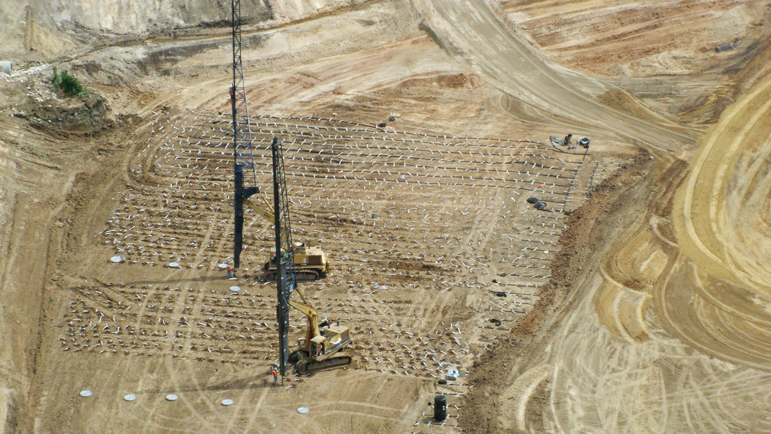
[I] PVD Installation
PVDs are installed by a hollow steel mandrel encasing the wick drain material. The mandrel is driven into the ground by a stitcher attached to an excavator carrier, as seen in figure I. This is a vibrating force, but static options are also available for areas near underground utilities. At the base of the mandrel, the wick is looped through a steel anchor to secure the drain in place. Once the desired depth is reached, the drain is anchored and the mandrel is extracted. The mandrel is withdrawn 15 to 20 cm above the surface for the wick drain to be cut. If the soil the mandrel is driving into is exceedingly stiff, and the mandrel cannot be vibrated or hammered into the ground, predrilling may become necessary.
Depth of Installation
Drains are not likely to accelerate consolidation if induced effective stress is not greater than the preconsolidation stress. The optimum depth of the wick drains lies within the preconsolidation stress margin as the stress from the surcharge diminishes with depth. However, if there is a pervious soil layer below the preconsolidation margin, the wick drain should be extended into that soil layer. This will aid in assuring the discharge of the water [5].
Width of Installation
Soil strata are not defined as entirely uniform layers, therefore there may not be equal volumes of water to be drained. If some portions of a layer have a greater amount of drainage, the soil will settle to fill those voids. This leads to differential settlements and could prolong the consolidation time. To help avoid this issue, wick drains should be distributed across the entire footprint of an embankment and a small distance beyond. It is advised to place the outermost rows of drains between one third and one half of the proposed embankment's height beyond the embannkment. However when designing the wick drain’s layout, homogeneous soil can be assumed for simplicity [5].
Soil Properties
Design Parameters
The design of PVDs requires an evaluation of design parameters including soil and drain properties as well as the effects of PVD installation. The size of the project can influence the amount of effort needed for evaluation.
This section refers to the following project descriptions as defined by Rixner et al. (1986):
| Project Category | Description |
| A | Basically uniform soil (no varving, low to moderate sensitivity) Simple construction (no staged loading) PVDs few in number (length |
| B | Increased complexity, Intermediate |
| C | Unusual soils (varved, or high sensitivity) Staged loading, complicated construction PVDs numerous in number (length > 18m (60ft)) |
Soil Properties
All soil property values used in design of wick drains should be evaluated at the maximum vertical effective stress that shall be applied to the compressible soil in the field.
Coefficient of Consolidation for Horizontal Drainage (ch) & Coefficient of Permeability for Horizontal Seepage (kh)
Category A projects may use ch conservatively estimated as approximately cv (kh/kv = 1) measured in lab from one-dimensional consolidation tests (ASTM D2435). There are estimates for kh, but field and lab measurements should be taken to compare and adjust the value [9].
ch = (kh / kv) * cv (8)
Category C projects should have more accurately estimated values for ch using any variation of methods. In-situ piezometer probes and analysis of pore pressure dissipation curves may be of reference. In-situ determination of kh by small-scale pumping tests in piezometers or self-boring permeameters can be used with laboratory mv values to form a relationship for ch [9].
ch = kh / (mv * yw) (9)
Where:
ϒw = unit weight of water
Mv = coefficient of volume change
It is generally recommended to employ conventional consolidation tests to measure cv combined with field and laboratory investigations to estimate kh/kv and then evaluate ch via the Category A equation.
Coefficient of Permeability in the Horizontal Direction in the Disturbed Soil (ks)
The Ratio of kh/ks range 1-5, and is expected to vary with soil sensitivity and the presence or absence of soil macrofabric [9].
Drain Influence Zone
The drain influence zone (D) is a function of drain spacing (S) only. Vertical drains are commonly installed in square of triangular patterns. Square pattern layouts have greater ease and control in the field. However the triangular patterns are preferred to provide more uniform consolidation between drains. Shown below are diagrams of the square and triangular patterns [9].
| Pattern | D as a function of S |
| Square | D = 1.13*S |
| Triangular | D = 1.05*S |
|
|


[J] Installation Patterns
Effectiveness of Prefabricated Vertical Drains (PVDs)
In order for effective expedition of the consolidation process, the PVDs must accept water from the surrounding soil, and discharge it. The initial design conditions and changes in these factors throughout the length of the project will affect the consolidation rate/success of the project.
Water Flow into Drain
Hydraulic Conductivity
The hydraulic conductivity of the soil surrounding the drain will control the rate at which water can enter the drain and relieve pore water pressures in the soil.
Smear Zone
The installation of PVDs require the use of a steel mandrel, which firmly clamps the drain during its insertion into the ground. Accompanying the mandrel, is an anchor plate fixed to the bottom of the drain, which serves to prevent soil from entering the drain and to keep the drain in place upon removing the mandrel. Below is a simple diagram of the anchoring system [11].
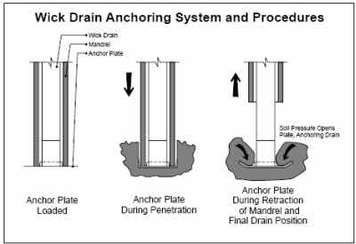
[K] Drain, Mandrel and Anchor Plate
As the mandrel is pushed downward and upon its removal once the drain is in place, it disturbs the soil surrounding the drain producing shear strains and displacement that decrease its hydraulic conductivity.
Minimizing the mandrel cross sectional area will reduce potential for soil displacement and disturbance. It may be suitable to taper the mandrel tip, as long as the stiffness is not sacrificed. For soil profiles with many different layers, large kh/kv ratios, the laying may enhance horizontal permeability. It is possible to retard the lateral seepage of pore water into the drains by smearing of pervious and less pervious layers. Static pushing is preferred to drive or vibrating the mandrel in sensitive soil, but may cause buckling or wobbling of the mandrel. An idealization of the mandrel disturbance area is shown in Figure L.
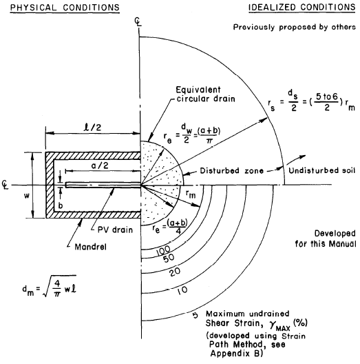
[L] Approximation of the Disturbed Zone Around the Mandrel
Although there have been numerous studies conducted to assess properties of the smear zone including range, shape, and effect on hydraulic conductivity, there is no precise consensus among researchers. Nevertheless, some generalities are listed below:
The larger the mandrel, the larger the smear zone.
The shape of the mandrel affects the shape of the smear zone
Square/Circular Mandrel – Square/Circular Smear Zone
Rectangular Mandrel – Ellipsoidal Smear Zone
The outer boundary of the Smear Zone has been found to range from 4-18 times the equivalent mandrel radius.
The overlap of smear zones from adjacent drains complicates smear zone calculations further [3]
Discharge Capacity
Design
The design discharge capacity of the drain is a function of its cross-sectional area (core available for flow). This capacity can and will likely be reduced immediately upon installation and over the lifetime of the project.
Installation
The installation of the drains is a rough process and is not only destructive of the installation equipment itself (mandrels often need be replaced over the course of a project, and installation equipment repaired), but is also presents the critical case for the mechanical properties of the drain. Grab and puncture tests per ASTM standard of the geosynthetic material are important in this regard [7].
Reduction With Time
Over the lifetime of the project a number of factors can reduce the discharge capacity of the drain and slow down the consolidation process.
Clogging
Clogging of the PVD can significantly reduce the discharge capacity of the drain. A filter with appropriate properties (such as AOS – Apparent Opening Size, per ASTM D 4751) will pass water, while retaining clay particles and limit clogging. The larger the drainage channel (cross-sectional area of the drain), the less the discharge capacity will be effected by clogging, all else held equal [8].
Bending/Kinking
As the soil consolidates, reducing the thickness of the clay layer, the drain undergoes bending and/or kinking deformation. The figure below idealizes some of the possible bending/kinking mechanisms [1].
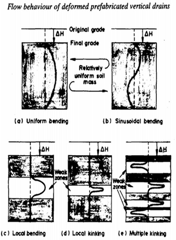
[M] Various Possible Configurations for Vertical Accommodation to Soil Settlement
Nguyen &Hung (2010), tested a variety of PVDs, and took photos of the deformations. They appear in Figure N.

[N] Deformation Patterns
Whether the drain kinks or bends depends on the flexibility of the drain and modulus of the surrounding clay [4]. A more flexible drain core will lead to greater reduction in discharge capacity [14]. Furthermore, sharp kinks will reduce flow through the drain more than gradual bends. [1]
Lateral Earth Pressures
Lateral earth pressures can cause the filter of the drain to pass into the core in a punching manner, reducing flow [11].
Biological Degradation
Biological and chemical activity can reduce discharge capacity as well [11]
Recent Development and Future of PVDs
Quality control of PVDs have improved in recent years with the incorporation of electronics to the installation equipment. Depth, installation force, GPS coordinates, and date/time information has been adopted in certain cases – such as the Craney Island project as documented by Goldberg (2013). Goldberg notes that this level of quality control is often not needed, as projects have consistently been successful without such measures [5].
As geosynthetics continue to improve on the basis of the targeted function, installation monitoring techniques become more sophisticated, and researchers continue to better understand factors that affect the discharge capacity of drains and the smear zone effect on hydraulic conductivity of the surrounding soil, surcharge loading with PVDs will only improve as a method of expediting consolidation of cohesive soils for settlement sensitive projects.
References
[1] Ali, Faisal Haji. "The Flow Behavior of Deformed Prefabricated Vertical Drains." Geotextiles and Geomembranes 10 (1991): 235-48. Elsevier. Web. 2 Apr. 2014
[2] Barron, R. A. (1948). "The equivalent diameter of the bandshaped drain." Trans. ASCE, Vol. 113,718-754.
[3] Basu, D., Basu, P. and Prezzi, M. (2013) A Rational Approach to the Design of Vertical Drains Considering Soil Disturbance. Sound Geotechnical Research to Practice: pp. 550-565. Doi: 10/1061/9780784412770.037
[4] Chen, Yun-Min, Xiao-Wu Tang, and Ning Jia. "Consolidation of Sensitive Clay with Vertical Drain." International Journal for Numerical and Analytical Methods in Geomechanics 31 (2007): 1695-713. Wiley InterScience. Web. 2 Apr. 2014.
[5] Fellenius, Bengt H. "Basics of Foundation Design." (2014): 104-21. Web. 19 Mar.2014."
[6] Foott, R. and Ladd, C.C., 1981, “Undrained Settlement of Plastic and Organic Clays”, JGED ASCE FT8, pp. 1079-1094
[7] Goldberg, A. D., et al. "Recent Advances in Prefabricated Vertical Drains."Ports 2013@ Success through Diversification. ASCE.
[8] Hansbo, S. (1979). “Consolidation of clay by band-shaped prefabricated drains.” Ground Engrg., 12(5), 16-25
[9] Holtz, R. D. "Preloading with prefabricated vertical strip drains." Geotextiles and Geomembranes 6.1 (1987): 109-131.
[10] Long, R., and A. Covo. "Equivalent Diameter of Vertical Drains With an Oblong Cross Section." Journal of Geotechnical Engineering 120 (1994): 1625-30. ASCE. Web. 6 Apr. 2014. ".
[11] Miura, N., and J. C. Chai. "Discharge Capacity of Prefabricated Vertical Drains Confined in Clay."Geosynthetics International 7.2 (2000): 119-35. International Geosynthetics Society. Web. 2 Apr. 2014.
[12] Rixner, J. J., Kraemer, S. R., and Smith, A. D. (1986). "Geocomposite Drains, vol. I: Engineering Assessment and Preliminary Guidelines." Federal Hwy. Administration Res. Rep. No. FHWA/RD-86/168, McLean, VA.
[13] Rixner, J. J., Kraemer, S. R., and Smith, A. D. (1986). "Prefabricated vertical drains, vol. II: summary of research effort." Federal Hwy. Administration Res. Rep. No. FHWA/RD-86/169, Washington, D.C
[14] Scott, R.F. (1963). Principles of soil mechanics. Addison-Wesles, Reading, Mass., 121-125
[15] Stapelfeldt, T. "Preloading and vertical drains." Electronic publication (2006)
[16] Suits, L.D., Gemme, R.L., and Masi, J.J. (1986). “Effectiveness of prefabricated drains on laboratory consolidation of remolded soils.” Consolidation of soils: testing and evaluation, ASTM STP 892, R. N. Yong and F. C. Townshed, eds., ASTM, Philadelphia, Pa., 663-683.
[17] Taube, Martin G., P.E., M.ASCE. "Prefabricated Vertical Drains: The Squeeze is On." Geo-Strata Mar. 2008: 12-16. Menardusa. Web. 6 Apr. 2014. ".
[18] Taylor, D. W. (1948). Fundamentals of soil mechcanics, John Wiley & Sons, Inc., New York, N.Y., 194-198
[19] Tran-Nguyen, Hoang-Hung. "Effect of Deformation of Prefabricated Vertical Drains (PVD) on Discharge Capacity and the Characteristics of the PVD Smear Zone." Diss. University of Wisconsin-Madison, 2010. Proquest. Web. 2 Apr. 2014.
[20] Tran-Nguyen, H. Edil, T. (2011) The Characteristics of the PVD Smear Zone. Geo-Frontiers 2011:pp. 748-757. Doi: 10.1061/41165(397)77
[21] Van de Griend, A.A., 1984, "Research into the Influence of Relative Compression of a Soil Layer and the Drain Deformation on the Discharge Capacity of a Number of Vertical Plastic Drains", thesis FOR THE Delft Technical University Specialist Group for Geotechnology
Additional references used to address the comments provided below:
[22] Davie, J.R., Lewis, M.R., Young, Jr., L.W. (1988), “Accelerated Consolidation of Soft Clays Using Wick Drains,” Second International Conference on Case Histories in Geotechnical Engineering, June 1-5, 1988, St. Louis, Mo., Paper No. 5.29, pg. 1019-1024
[23] Leonards, G.A. (1962), “Engineering Properties of Soils”, Chapter 2 in Foundation Engineering, edited by G.A. Leonards, McGraw Hill.
Figure and Table List
[A] Prefabricated Vertical Drains
http://ww1.prweb.com/prfiles/2010/06/15/1793074/WickDrain.jpg
[B] Cross-Section With and Without Vertical Drains
http://www.geosinindo.co.id/wp-content/uploads/2011/06/6-1.png
[C] Layfield Wick Drain Example
http://www.layfieldgeosynthetics.com/Content_Files/Images/Product/wick-3.jpg
[D] Geosupply Wick Drain Example
http://www.geosupply.asia/UploadFiles/2010325142857559.jpg
[E] Cross-Section of PVD
Barron, R.A. (1948)
[F] Flow Net for Flow to Oblong Drain from Circular Source
Barron, R.A. (1948)
[G] Plot of Equivalent-Drain-Diameter to Width-of-Drain Ration, d/b versus Thickness-of-Drain to Width-of-Drain Ration, t/v
Barron, R.A. (1948)
[H] Comparison of Equivalent Drain Diameters by Various Methods
Barron, R.A. (1948)
[I] PVD Installation
http://img.archiexpo.com/pdf/repository_ae/61481/vertical-wick-drains-89296_2b.jpg
[J] Installation Patterns
Holtz, R.D. (1987)
[K] Drain, Mandrel and Anchor Plate
Cramer (undated)
[L] Approximation of the Disturbed Zone Around the Mandrel
Holtz, R.D. (1987)
[M] Various Possible Configurations for Vertical Accommodation to Soil Settlement
Ali, Faisal Haji (1991)
[N] Deformation Patterns
Tran-Nguyen, Hoang-Hung (2010)
 Jenna Scorza
  Gregory Fox
Industry News


Events

12th International Symposium on Field Monitoring in Geomechanics 2026

DFI 50th Anniversary Conference on Deep Foundations

9th International Symposium for Geotechnical Safety and Risk

5th International Symposium on Frontiers in Offshore Geotechnics (ISFOG)

Pan Mediterranean Geotechnical Engineering Conference

The Third Vietnam Symposium on Advances in Offshore Engineering

4th Asia-Pacific Conference on Physical Modelling in Geotechnics (ACPMG 2024)

The 2nd GeoMandu: Geotechnics for Sustainable Infrastructures

5th International Conference on Transportation Geotechnics


6 COMMENTS
Nejan Huvaj*
Apr, 10, 2014 Congratulations to professor Zeccos for this initiative, and to you students for this nice piece of work. I would like to suggest to add a few words on "well resistance" and its relation to discharge capacity. My second suggestion would be to add references in paranthesis at the end of the sentence "The outer boundary of the Smear Zone has been found to range from 4-18 times the equivalent mandrel radius", referring to the researchers who suggested these numbers. And one final comment: my eyes looked for the work of Mesri and/or Indraratna in the reference list, you may want to consider. Again, well done! Jenna Scorza
Apr, 26, 2014 Dear Nejan Huvaj,Thank you for taking the time to review our project and adding your suggestions.
We are glad you pointed out some confusion in our referencing of the generalities of the smear zone. The citation [3] at the end of the section is meant to serve as the reference for the entire preceding paragraph. Basu (2013) outlines these generalities, and we found them to be approximately consistent with the works of others, with possibly a slight skew of researchers closer to the lower bound of the 4-18 range.
Thank you also for the suggestion of Mesri and Indraratna as sources to potentially have included. Although our project research efforts did not lead us to incorporate these authors, doing so definitely could have strengthened/supplemented our work in certain regards. Mesri’s work on the compressibility of clays, and characteristics of secondary compression provide background relevant to many aspects of a wick drain project and perhaps would have been most fitting to include in the our ‘Suitable Soils’ section. Indraratna’s works could be valuable in furthering our description of the smear zone, and including wick drain performance under cyclic loading as a separate subtopic.
Thank you,
Jenna and Greg
Edit Comment
Kiki*
Apr, 17, 2014 Well done!Prefabricated drains can also be considered in liquefaction remediation projects and their performance can be assessed using FEQDrain software.
I would also suggest adding a few numbers on the time required for consolidation with and without wick drains, taken from a real project.
Jenna Scorza
Apr, 26, 2014 Dear Kiki,Thank you for taking the time to review our project and adding your suggestion.
The “History” page has been updated and now includes a case history describing the time required for consolidation with and without wick drains. In this project wick drains were used effectively to cut down the consolidation time for 90% settlement by 25 times that of estimates for the wick drain-absent scenario. The case history is part of paper number 5.29 that was presented at the Second International Conference on Case Histories in Geotechnical Engineering, June 1-5, 1988, in St. Louis, Mo.
The Geoengineer.org website has some information on the implementation of prefabricated drains for soil stabilization in potentially liquefiable sites using FEQDrain software. The software can be used to analyze three dimensional pore pressure generation and dissipation in layered sand deposits with geocomposite vertical drains for liquefaction mitigation. If you would like to reference this software, it is licensed as freeware, and can be found in the following section: Home / Software / Ground Improvement / Freeware / FEQDrain.
Thank you,
Jenna and Greg
Edit Comment
Sally Simpson*
Apr, 23, 2014 Thank you for the project. Can you provide more information on the flow capacity of the wick drains, i.e., what is their discharge capacity. Also, how is the geotextile around the wick drain selected to avoid clogging by the clay particles? Jenna Scorza
Apr, 26, 2014 Dear Sally Simpson,Thank you for taking the time to review our project and adding your suggestion.
Miura & Chai (2000) provide specifics about both discharge capacity and geotextile properties affecting their resistance/proneness to clogging. They ran tests on four different PVD specimens that varied in properties (including mass per unit area, thickness, polymer, and manufacturing process) using the same testing apparatus and remolded Ariake clay (57% clay, 41.7% silt, 1.3% sand particles; LL=105%, PL= 42.8%). The results indicate initial discharge capacities ranging from approximately 100 m3/ yr to 400 m3/yr, which after periods of 100-300 days reduced by 5 times in some cases. Miura and Chai (2000) attribute the significant reduction in discharge capacity with time predominantly to clogging of the PVD drainage channels, and marginally to creep deformation of the PVD filter.
Holtz (1987) describes the three important design criteria for a geotextile: soil retention (piping resistance), permeability, and filtration (clogging resistance). The Apparent Opening Size (AOS) of the geotextile as determined by ASTM D4751 is a crucial property for these considerations and is recognized as the “largest opening dimension available for soil to pass through”. Holtz (1987) mentions that specifications for filtration requirements including O95 ≥ 3D15 and/or O15 ≥ 3D15 might be used, particularly for potentially problematic gap-graded and silty soils. Per the requirements, O95 and O15 are related to the AOS, and are the opening sizes of which 95% and 15%, respectively, of those in the geotextile are smaller. Furthermore, Holts (1987) recommends the Gradient Ratio test, using representative soil samples, as another filtration/clogging measure.
Thank you,
Jenna and Greg
Edit Comment