Contents [show]
Introduction
Soil Vapor Extraction is a common remediation technology for treating soils in the vadose zone that are contaminated with volatile compounds. In general, soil vapor extraction (SVE) consists of a screened well (or wells) placed in the vadose zone, which is either contaminated or overlying a contaminated groundwater source. Air is drawn through the contaminated soil, where it mixes with contaminated vapors and is then drawn out through the well. At the ground surface, the contaminated vapor is treated and then released. Figure 1 presents a schematic of a generic SVE system. This has been proven to be an effective treatment method for many volatile organic compounds, among other contaminants, at many sites, worldwide. In the following sections, a fundamental background of SVE is presented, followed by an overview of the design and operation of an SVE system. Advantages and disadvantages of the method are highlighted and two representative case studies are presented.

Figure 1. Schematic of a Generic SVE System (USACE, 2002)
Contaminant and Site Suitability
Types of Contamination for Which SVE is Suitable
Typical contaminants that soil vapor extraction is applicable for are volatile organic compounds. Volatile organic compounds (VOCs) are compounds that have a low boiling point and a high vapor pressure. This low boiling point causes the molecules within the compound to evaporate from the liquid and enter into the air. According to the World Health Organization (WHO), volatile organic compounds are classified by the boiling point to which they volatilize to the atmosphere (USEPA 2012a). These classifications are divided into three categories; very volatile organic compounds (VVOCs), volatile organic compounds (VOCs), and semi volatile organic compounds (SVOCs). The more volatile the contaminant is, the better SVE is at removing that particular contaminant. Table 1 provides the VOC classification with their respective boiling points.

Table 1. VOC Classifications (USEPA, 2012a)
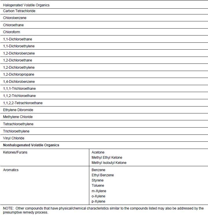
Table 2. VOCs Considered to be Amenable to SVE (USACE, 2002)
Contaminants with this type of classification include petroleum and chlorinated compounds. Table 2 provides a list of constituents that are suitable for SVE remediation systems. The sources of these contaminants are usually caused by leaking underground storage tanks (USTs), fueling sites, and dry cleaners. Some of the contaminants that are present in petroleum are BTEX compounds; benzene, toluene, ethylbenzene, and xylenes, where a common constituent that is leaked or spilled from dry cleaning operations is tetrachloroethene or perchloroethylene. The boiling points for these substances range from 80°C to 144°C, which makes them all volatile organic compounds (Table 3).
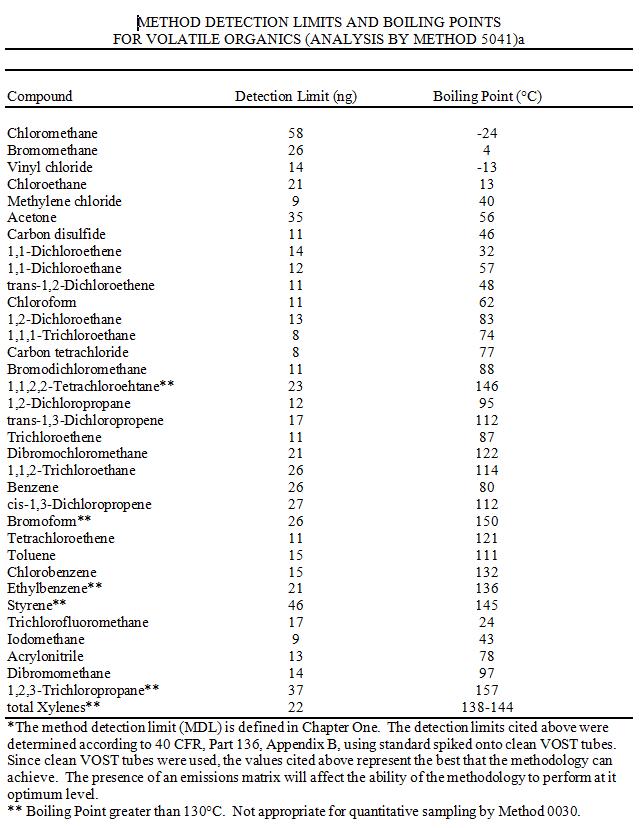
Table 3. Method Detection Limits and Boiling Points for Volatile Organics (USEPA, 1996)
Site Suitability
When determining the appropriateness of SVE for a particular contamination site, the soil type, permeability, and the level of the groundwater table are necessary factors to consider. These factors are important because this process is applicable when the soils are fine to medium sands, highly permeable to permit greater air flow for better vapor extraction, and only appropriate in unsaturated soils (Sharma and Reddy 2004). These soil types typically have a permeability greater than 10-6 cm/s, which allows for the contaminated vapor to flow around the soil particles. SVE is best suited when the groundwater table is greater than 10 feet below the ground surface because upwelling can occur within the wells which can prevent soil vapor flow from occurring (USEPA 2012b). A pump may be necessary when trying to implement SVE in an area where the water table is higher or if upwelling occurs near the extraction wells in order to draw down the water table so that the vadose zone is increased. If the groundwater is contaminated as well a dual phase extraction (DPE) remediation technique should be used in order to extract the contaminated water and vapor which will go through a separator before treatment (USEPA 2012c).
Predominant Processes in SVE
SVE is governed by four different processes, volatilization, advection, diffusion, and desorption (Sharma and Reddy 2004). Figure 2 shows a typical SVE setup and the processes that take place during the remediation technique.
- Volatilization is the dominant process within the soil vapor extraction system because the contaminants are volatile substances that readily evaporate from the surface of particles. Therefore, the contaminated vapor within the soil will be removed by the extraction wells.
- Advection is the transport of a substance through a medium, whether it be a fluid or air. In the case of SVE it is the transport of contaminants through air. The contaminants within the vadose zone move due to a negative pressure gradient within the soil caused by the vacuums applied to the extraction wells. This negative pressure gradient causes the contaminated air to migrate towards the extraction wells.
- Diffusion is a process where a substance will spread out or “diffuse” into the surrounding area. Diffusion occurs due to a negative concentration gradient caused by the extraction wells, so the contaminants with the higher concentration will diffuse toward the wells where there is little to no concentration of contaminants. Diffusion occurs until there is no concentraion gradient within the soil.
- Desorption is the process by which a substance is removed from a surface. Due to the applied vacuum, the soil-air is removed from the surface of the soil and moves throughout the void spaces of the soil particles towards the extraction wells because of a concentration gradient within the soil.

Figure 2. SVE Transport Processes (USACE, 2002)
Design and Operation of SVE Systems
The design of soil vapor extraction (SVE) systems is largely empirical due to the great number of parameters and mechanisms involved. Accordingly, the commissioning of each SVE system should be preceded by an involved screening process, which transitions into a pilot-scale test at the site of interest. The following sections provide a summary of accepted methods for determining if SVE is an appropriate remediation technology for a given site and key components of pilot-scale testing. This is followed by a brief overview of the design of the full SVE system as well as operation and monitoring considerations. Finally, some of the potential modifications of SVE are discussed.
Determination of Applicability of SVE
The first step in designing a SVE system is determining if in fact it is an appropriate technology and is capable of removing the desired amount of contaminant from the site. Following the initial investigation of the site and determination of the extent and composition of contamination, the decision tree presented in Figure 3 can be used as an initial indicator of whether or not SVE may be applicable. The second to last box of the flow chart, labeled “Evaluate Relative to a Variety of Site Specific Factors, Considering Experience at Other Sites” entails an in-depth screening process to further ensure that SVE is viable, and is discussed below.

Figure 3. Technology Screening Decision Tree (USACE, 2002)
(SVE: Soil Vapor Extraction
BV: Bioventing)
Johnson et al (1988) present a comprehensive, and widely referenced, set of mathematical models that can be used as screening tools for SVE. The authors identify three primary factors that strongly influence the applicability of SVE and provide equations to model them. The three factors are: 1) vapor flow rate, 2) contaminant concentration, and 3) the location/setting of the contamination relative to the desired flow path. For steady state conditions, the radial pressure distribution around the well, the radial velocity distribution, and the vapor flow rate can be described by equations 1, 2, and 3, respectively. Johnson et al also present the transient forms of these equations as well as the derivations.
(1) 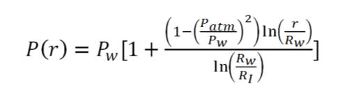
Where Pw: pressure at the vacuum well
Rw: well radius
RI: radius of influence
Patm: atmospheric pressure
r: radius from the well
(2) 
Where k: soil permeability
μ: vapor viscosity
(3) ![]()
Where: H: screened length of the well (within the vadose zone)
Using these equations, for a homogenous soil system, the vapor flow rate, velocity distribution around the well, and vapor travel time from a given point to the well, can be estimated. For SVE systems through layered soils, the total flow rate is simply equal to the sum of the individual flow rates (according to equation 3) for each layer. It is also critical to understand how the concentration of the contaminant will change with time during the vapor extraction process. Johnson et al (1988) present a solution to the governing vapor phase concentration equation which can be incorporated into the mole balance equation (equation 4). This must be solved numerically to obtain the change in concentration with time. Figures 4 and 5 present examples of results from this type of analysis. They are the mass loss rates with time and concentrations with time, respectively.
(4) 
Where Mi: total number of moles of component i
Ci: molar concentration of i
Bi: rate of degradation (biological or chemical) of i
t: time

Figure 4. Predicted Mass Loss Rates for a Hypothetical Venting Operation (Johnson et al 1988)

Figure 5. Predicted Soil Concentrations of Hydrocarbons for a Hypothetical Venting Operation (Johnson et al 1988)
Finally, it is important to consider the flow path, relative to the contamination, that will be induced by the proposed SVE system. The mathematical models presented above for factors (1) and (2) are based upon assumptions of vapor flow through homogenous soils with homogenous contamination. This however is often not the case. The contaminant may be spread through various soil layers and/or may exist below the ground water table or in a relatively impermeable layer. Under these conditions, the vapor extraction must take place through diffusion, instead of simply advection through unsaturated soils. Figure 6 illustrates some of the different scenarios under which SVE may take place. This must be understood for the site of interest and the boundary conditions of the mathematical models used to predict vapor flow and concentrations must be adjusted accordingly.

Figure 6. Scenarios of SVE flow paths (Johnson, 1990)
Following determination of the three factors presented above, an informed decision can be made to determine if SVE is appropriate for the given site. The models created can be used to estimate how an SVE system would perform. Johnson et al (1990) present a series of six basic questions that need to be answered alongside these factors to verify that SVE is feasible. They are as follows:
- What are the expected contaminant vapor concentrations (at the beginning of extraction)?
- Is the concentration great enough to achieve acceptable contaminant removal rates?
- What vapor flow rates can be achieved?
- Will the concentration and vapor flow rates produce acceptable removal?
- What residual will be left in the soil following remediation?
- Is there potential for any negative impact to the site or surrounding sites due to the SVE process?
Of these questions, Johnson et al identify 2) and 4) as being critical to the advancement of the project beyond the screening phase. If the concentration of contaminant within the soil is too low for the SVE process to remove a significant portion of the contaminant, a different remediation option must be considered. When examining this, the biodegrability of the contaminant must be considered, since it may result in changes to the achievable removal concentrations as the contaminant degrades. Also, with the available equipment and supplies, it may not be possible to achieve high enough flow rates to result in adequate contaminant removal. This also is grounds for abandoning SVE as a remediation option. There is also potential for the SVE operation to negatively affect the site or neighboring sites. One example of this is contaminants from neighboring sites being drawn in to the site of interest by the vapor flow or as a result in change in ground water table in conjunction with SVE. These types of issues however can be remedied with passive wells and by diligent monitoring during the operation of the remediation. A passive well is a well which has no pump but enhances airflow from the ground surface, allowing the designer to better control the subsurface airflow.
Pilot-Scale Testing
Once it has been determined that, according to the predictive models, SVE is an appropriate remediation technology, it is necessary to perform pilot-scale testing at the site. Due to the complexity of the process, predictive models may not capture all of the important aspects of the system. For this reason, pilot-scale tests are always conducted prior to the full design and implementation of a SVE system. In addition, bench-scale column tests, air permeability tests and ground water pumping tests are often conducted.
Pilot-scale tests typically consist of a single extraction well with additional wells for sampling and monitoring. Figure 7 presents a schematic of a typical pilot test setup. USACE (2002) identifies the following measurements that should be taken during a pilot-scale test: airflow rates, pressure levels, soil/air temperature, soil moisture levels, effluent contaminant concentrations, and quantity and composition of liquids retrieved from the air/water separator. The results of the pilot scale test are used to refine the site model that was developed during the screening process. Of particular interest from a pilot test is the time that it takes for the system to reach steady-state removal concentrations. Since this is dependent on a wide range of factors, it is very difficult to accurately model. A pilot test is run at least until the baseline concentration is reached. Typical pilot tests are completed within hours, but may take days, or even longer. Performing Modified Active Gas Sampling in conjunction with the pilot-scale testing can reduce the time needed for the test. In addition to helping refine the predictive models, the pilot test may also be used to refine the understanding of where the contaminant is located, since the initial site investigation can only provide estimates. This information can be gathered from the removal concentration-time history taken from the pilot test. If the concentration increases with time, it indicates that the pilot extraction well is located at a distance from the contaminant center, while a decrease in concentration with time indicates that the well is near the center of the contaminant. Finally, the pilot test can be used to monitor potential upwelling of the ground water table due to the vapor extraction process.

Figure 7. Typical pilot test setup schematic (USACE, 2002)
System Design
Once the pilot test has been conducted the complete SVE system can be designed. Using the predictive models from the screening process and the information gathered from the pilot test, the various aspects of the system, including well depth, screening depth, number of wells and spacing, well arrangement, pump/blower capacity, and above ground treatment, can be arranged to optimize the removal of contaminants from the soil. This is a complicated process which is largely empirical and requires vast experience and expertise. In order to illustrate this complexity, the list of professionals that USACE (2002) recommends be a part of the design team is reproduced below:
- Environmental/chemical engineer
- Health and safety specialist
- Mechanical engineer
- Regulatory specialist
- Chemist
- Cost engineer
- Geologist/geotechnical engineer/hydrogeologist
- Civil/structural engineer
- Soil scientist/soil physicist
- Electrical engineer
A critical component of the design of the SVE system is the number of extraction wells. There are multiple methods for calculating the number of wells, all with varying assumptions. Johnson et al (1990) suggest computing the number of wells using three methods, described here, and selecting the largest of the three. The first method is to simply divide the acceptable removal rate by the estimated removal rate for one extraction well. This neglects the change vapor concentration with time. The second method is to use the mathematical models presented in the screening process to calculate the required number of wells. Depending on the extent to which the models have been developed, and what assumptions were made, this approach may allow for a better representation of the transient nature of the process. The third approach is to divide the area of the contamination by the area of influence of a single extraction well.
Once the number of wells has been determined, their configuration and spacing must be designed. This will be heavily dependent upon how the desired vapor path will travel relative to the contaminant, as well as soil stratigraphy. Well spacings typically range between 15 and 100 feet (Hutzler et al, 1991). There are multiple types of configurations that may be used, including vertical wells and horizontal trenches, capped systems, systems which cycle between wells at a given site, and single well systems. Figure 8 illustrates some of the variations in possible well configurations. It should be noted that while designing the configuration, care must be taken to avoid stagnant zones between wells.

Figure 8. Examples of venting well configurations (USACE, 2002)
Upon extraction from the subsurface, the contaminant vapors must be treated prior to release. Several methods exist for the above ground treatment of offgas. Table 4 presents a table of VOC treatment technologies, reproduced from USACE (2002). Of these technologies, Johnson (1990) indicates that the ones most commonly used for SVE systems are vapor combustion, catalytic oxidation, carbon beds, and diffuser stacks. As indicated in the USACE table, each option has its advantages and disadvantages. Diffuser stacks are not listed in the table, because they do not actually treat the vapors, but rather release them in a controlled manner. This option is often not permitted and the health and safety risks associated with it must be carefully considered.
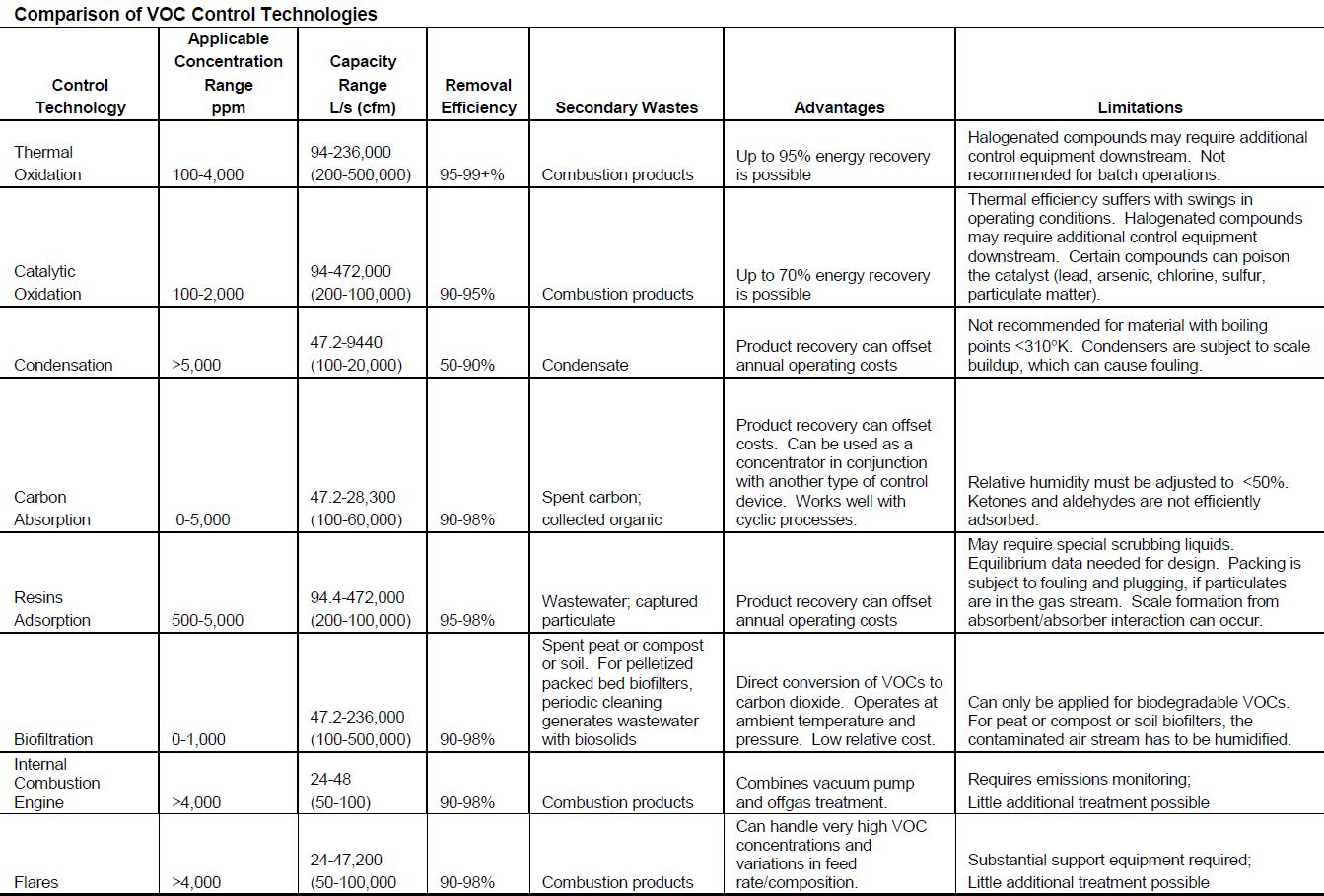
Table 4. VOC Treatment Technologies (USACE, 2002)
The design considerations presented here are only a brief overview of the design process that takes place for SVE systems. In addition to the relatively simple mathematical models that have been presented, several sophisticated tools are available to aid in the design process. The USEPA has made available a software program, HyperVentilate, for guiding engineers through the design process. This software is based on the approach presented by Johnson et al. Three dimensional finite difference programs, such as VENT3D, have also been used for modeling SVE applications (e.g. El-Beshry et al, 2000). However, many publications on the topic of SVE design stress the fact that experience and good engineering judgment are paramount in designing a successful SVE system.
System Operation and Monitoring
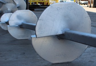
Following completion of the design, the SVE system is ready to be constructed and extraction can commence. (Figure 9 presents an image of an operating SVE system) However, the operation is still a dynamic process and parameters are still subject to change. Extensive monitoring must be conducted throughout the operation of the system for multiple reasons. The operators must verify that the equipment is working properly and must adjust the operation (well pressures, etc.) to further optimize the removal of the contaminants. Finally, the monitoring results are used to determine when the remediation is complete and the system can be shut down. Table 5 presents a list of items that USACE suggests be monitored throughout the operation. Of these measurements, Johnson et al (1990) suggest that, at the very minimum, vapor flow rates, pressure readings, vapor concentrations and compositions, temperature, and water table levels, must be taken.

Figure 9. Image of SVE System During Operation (serc.carleton.edu)
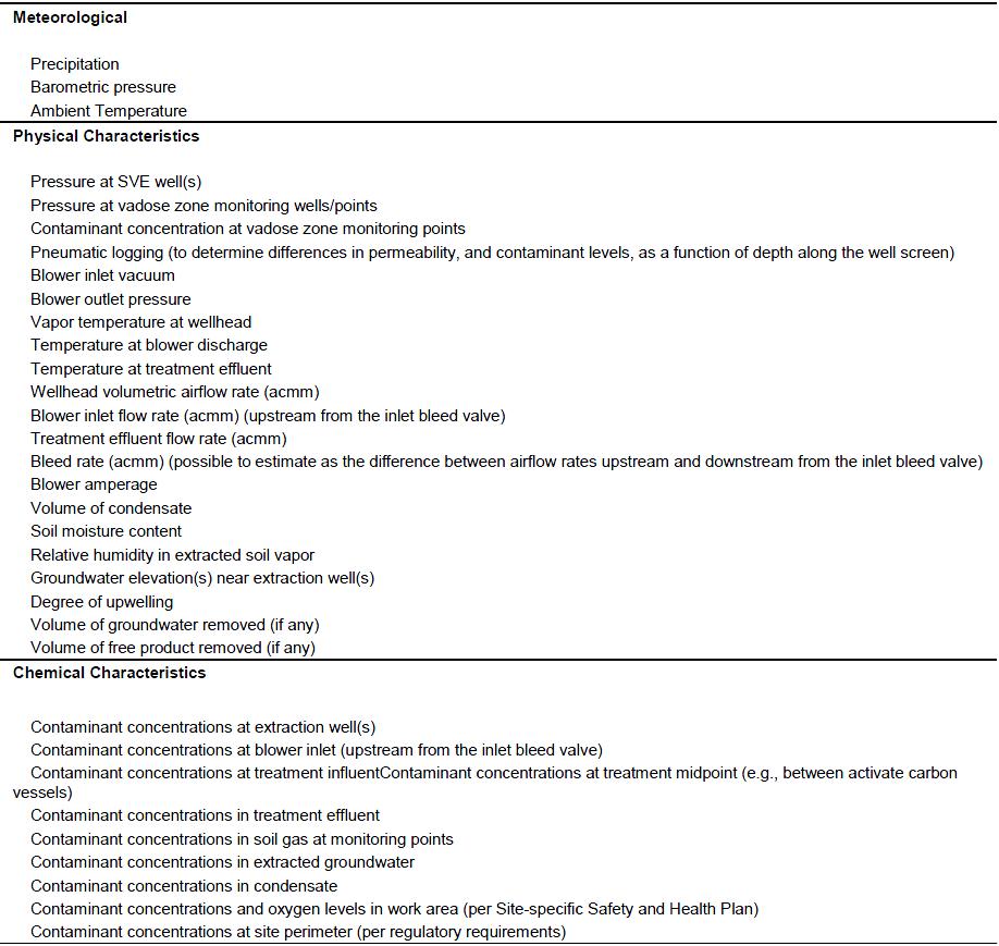
Table 5. Suggested SVE System Monitoring (USACE, 2002)
The duration and cost of an SVE operation vary widely from site to site, depending on numerous factors. The operation of the systems is typically on the order of years. A summary of 12 remediation cases presented by the Federal Remediation Technologies Roundtable (USEPA,1998) indicated project durations ranging from 8 months to 8 years. A table from the same report summarizing the cost of the 12 projects is presented in Table 6. As the table shows, the total cost of the projects ranged from $76,000 to $43 million. The cost per unit of treated soil also varied widely, with the lowest being $0.35/lb and the highest being $220/lb.
Part of the reason for the wide range in operation duration and costs is the fact that there are several modifications and extensions of conventional SVE that may be used. SVE is very frequently used in conjunction with some other remediation technology such as air sparging or bioventing (Hutzler et al, 1991). Air sparging is a similar method to SVE, but air is injected below the ground water table to force volatile contaminates to rise to the top of the water surface, where they can then be extracted by SVE. SVE may be performed in above-ground soil piles in cases where in-situ remediation is not feasible. The contaminated soil is excavated and stockpiled on the surface with a series of horizontal extraction trenches, as opposed to the conventional vertical wells. Also, despite the fact that the information presented in the screening process suggested that SVE may only be used for formations with high permeability, the USEPA has conducted SVE at low permeability sites by using hydraulic fracturing enhancement, in order to allow vapor pathways (Frank and Barkley, 1995). Overall, SVE is a very versatile and effective remediation option.
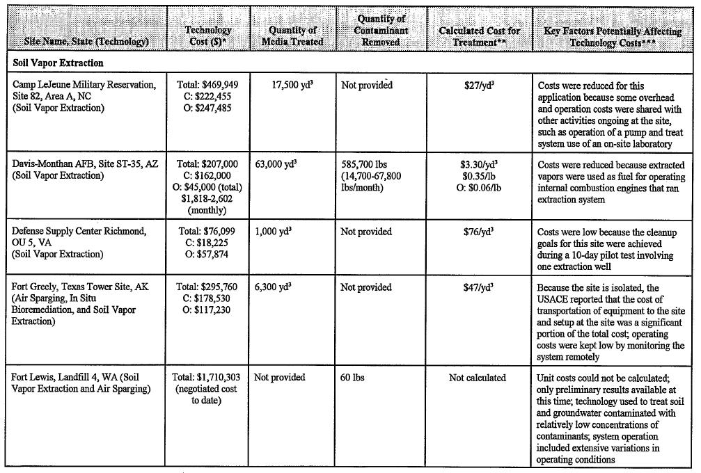

Table 6. Summary of Cost Data for Several SVE Projects (USEPA, 1998)
Advantages and Disadvantages of Soil Vapor Extraction
Advantages
There are many advantages to using the soil vapor extraction system as a method of remediation for a contaminated site. Some advantages may include the ease of installation due to construction materials being readily available. In addition, the ease of installation could decrease the amount of disturbance that occurs at the contamination site. Another advantage to using SVE is that this remedial technology is easily coupled with other techniques, such as air sparging, it can be used when the ground water table is at a depth where the extraction wells could draw water into them. Air sparging involves injecting contaminant free air into the injection well in order to transfer the contaminant from the dissolved state into the vapor state to allow for extraction. One more benefit is that the system is easily monitored, allowing the treatment time to be relatively short and inexpensive to implement compared to other techniques (Sharma and Reddy 2004).
Disadvantages
Although there are some advantages to choosing a soil vapor extraction system as a remediation technique, there are some disadvantages as well. One disadvantage is the system is applicable only for unsaturated soil and soils with high permeability. Saturated soils cause problems with SVE because of the amount of water that may get into the extraction wells and prevent vapor extraction, and low permeability soils do not allow for sufficient air flow for the vapors to be extracted and treated. Another disadvantage is that during excavation, contaminated air may escape into the atmosphere that should require treatment. The air emission treatment systems may require permits and a large amount of land use may be necessary for adequate treatment facilities and therefore may increase cost (Sharma and Reddy 2004).
Selected Case Studies
Camp LeJeune Military Reservation, Onslow County, North Carolina
Camp LeJeune is a United States Marine Corps military reservation located in Onslow County, North Carolina. The cleanup of contamination at the site is documented by the USEPA (1998) and is summarized here. From the time the camp was established in 1941 to the 1980s, a portion of the site, named Site 82, was used as a military disposal area. This disposal area is underlain primarily by fine- to medium-grained sands with traces of clay and silt. The ground water table is at a depth of approximately 18 feet below the ground surface. Throughout the site’s use as a disposal location, drums and debris were buried and left on the surface. The disposal resulted in contamination of both the groundwater and the soil with various VOCs. The main contaminants were Trichloroethene (TCE), Tetrachloroethene (PCE), and Benzene, with TCE being the most prevalent. Maximum concentrations of the contaminants were TCE: 1800 μg/kg, PCE 16.3 μg/kg, and benzene: μg/kg.
Owing to the soil conditions and nature of contamination at the site, soil vapor extraction was an appropriate remediation option. The system installed at the site consisted of eight vertical extraction wells, one horizontal injection well and 32 soil probe clusters. The extraction wells were installed to depths of approximately 15 to 16 feet. Upon extraction from the subsurface, vapors were passed through a vapor-liquid separator, after which the vapors were treated using activated carbon. The liquid effluent was transported to the groundwater treatment plant that was being used to treat the contaminated groundwater at the site. The system was operated from March 1995 to October 1995, with the startup and optimization process taking approximately 1 ½ weeks. Table 7 presents a breakdown of the costs involved with the project. The total cost of the project was nearly ½ million dollars and was ultimately a success.


Table 7. Cost breakdown of SVE at Camp LeJeune (USEPA, 1998)
The goals of the remediation project, in accordance with regulatory requirements, were to reach the following concentrations: TCE: 32.2 μg/kg, PCE: 10.5 μg/kg, and benzene: 5.4 μg/kg. All of these requirements were met and the SVE system was decommissioned. By the end of the project 17,500 yd3 of soil were successfully treated. One contributor to the success of the Camp LeJeune SVE operation was that it was performed in conjunction with an extensive ground water treatment operation. Much of the resources, as well as overhead, between these two projects could be shared. Camp LeJeune is an example of using traditional SVE as a cost-effective and relatively quick remediation technique.
Former Rail Yard Locomotive Fueling Area, Upstate New York
A former locomotive fueling area (FLFA) had a locomotive operation that included rail car and engine repair and refueling of locomotives. This case study is thoroughly documented by Compston et al (2006) and is summarized here in order to illustrate a typical case of SVE in conjunction with other remediation technologies. Operation of the FLFA ceased in the 1980s and the refueling equipment removed from the site. Petroleum products and light non-aqueous phase liquid (LNAPL) were found in the subsurface during the 1980s. To remedy the affected soil and groundwater, a combination of air sparging (AS) and soil vapor extraction (SVE). Air sparging will provide oxygen to the microorganisms capable of degrading the diesel fuel and volatilizing the petroleum compounds and soil vapor extraction will remove the volatilized diesel compounds from the subsurface.
The soil was characterized as fine-to-coarse sand and gravel with a layer of silt below at a depth of 16 to 18 feet below the ground surface (bgs). The hydraulic conductivity of this soil was found to range from 10-3 cm/s to 10-1 cm/s and the effective porosity was 0.25. In addition, the groundwater was located at a depth of between 8.5 and 13 feet bgs. The average horizontal groundwater velocity was approximately 0.3 ft/day with a directional flow to the south towards the Susquehanna River located at a distance of approximately 2,500 feet away from the remediation site.
The amount of petroleum contaminated soils was found to cover an area of about 120,000 ft2, within the FLFA the contaminated soil went to a depth from 2.5 ft bgs to 14 ft bgs, and areas down gradient of the FLFA the soils were found to be limited by the smear zone. The smear zone is the zone of vertical fluctuation of the water table, which ranges from 8.5 ft bgs to 13 ft bgs. So the total volume of the petroleum contaminated soils ranges from 300,000 ft3 to 1,680,000 ft3.
To treat the entire area, one treatment system was placed on the north side of the tracks and one on the south side. Each of these plants included SVE and AS blowers, system controls, and activated carbon treatment for SVE off-gas, as well as eight SVE-AS wells. On the south side of the tracks, there were also 20 biosparge (BS) wells that were installed to create a positive dissolved oxygen (DO) barrier from the migrating contaminants. The extraction rates for SVE wells were 30 cfm, AS well were 10 cfm, whereas the extraction rates for the BS wells was only between 1-2 cfm.
VOC and SVOC analyses were performed semi-annually from two locations on the north system and two locations on the south system. All four locations were soil samples taken from the area of influence of each respective area. In October 2002 it was found that the concentration of VOCs found in the area of influence from the north system were approximately 22,000 μg/kg, and the south systems concentrations were 41,000 μg/kg and 23,000 μg/kg. By June 2004, these concentrations had reduced to non-detectable concentrations on the north system, and non-detectable concentrations and 90 μg/kg, respectively, on the south system. In addition, total SVOC concentrations on the north system had declined 99% and 14% while concentrations on the south system had declined 98% and 95%. The lower percentage of decrease on the north system is due to a lower initial concentration of SVOC in that area.
For this specific remediation system, it was necessary to take groundwater samples from the wells within the area of influence in addition to down gradient of the treatment system. Initially, the four wells contained groundwater where one or more of the regulatory VOC and SVOC compounds were in excess of the groundwater standards. VOC concentrations decreased between 100% and 19%, where the average decline for the wells was 84%. Furthermore, samples collected from the wells within the down gradient of the treatment area SVOC concentrations were found to have been reduced by 100 % and 52%, with the average reduction being 84%. These decreases showed that after remediation of the site there were no VOCs or SVOCs in excess of the regulatory standards.
During the course of the remediation process, the SVE system was monitored and extraction rates measured. It was found that approximately 1,000 pounds of petroleum mass was removed over a 24 month period. The highest percentage of the removal took place within the first seven months of operation (from May to November 2002), where the largest mass removal took place from July 2002 and September 2003.
One important process in this system was the injection of oxygen into the subsurface to accelerate the metabolism of the microbial population that are responsible for the breakdown of diesel fuel in the soil. Between the months of May and October 2002, the bacterial population increased by two orders of magnitude in the saturated zone, three orders of magnitude in the unsaturated zone within the treatment area. Down gradient of the treatment area, the unsaturated zone did not show a significant change in bacterial population. Since then, the bacterial populations have declined, but that is probably due to the decrease in diesel fuel within the area.
The total project cost was estimated to be less than $350,000, which includes $235,000 being spent on the SVE-AS remedial program and $65,000 of that being spent on the treatment buildings. If the remediation process was to be excavation and off-site disposal of the contaminated soil, the project cost would be estimated to be $3.7 million. Therefore, choosing the SVE-AS system, significantly reduced the total project cost. In addition, there was cost reduction due to the system being shut down during colder winter months. This operational shut down was considered to be adequate given that microbial biodegradation is best in temperatures greater than 10°C.
The remediation of the petroleum contaminated site was successful due to the use of air sparging and soil vapor extraction. This success is largely due to the fact that there were multiple systems in place, including microbial degradation of the petroleum compounds, volatilization, and activated carbon capture. To determine the overall success of the remediation process, continued monitoring of the site will take place to ensure that the regulated VOC and SVOC compounds have been removed to the necessary standards, or below.
Recommended Reading
Technical Background
- Otten, Alma, Arne Alphenaar, Charles Pijls, Fank Spuij, and Han de Wit. (1997). “In Situ Soil Remediation.” Kluwer Academic Publishers., The Netherlands. 34-40.
- Kostecki, Paul T. and Calabrese, Edward J. (1992). “Contaminated Soils: Diesel Fuel Contamination.” Lewis Publishers, Inc., Chelsea, MI. 81-113.
Design Guidelines
- Johnson, P.C., C.C. Stanley, M.W. Kemblowski, D.L. Byers, and J.D. Colthart (1990). “A Practical Approach to the Design, Operation, and Monitoring of In Situ Soil-Venting Systems” in Ground Water Monitoring Review, 10(2), 159-178.
- USACE. (2002). “Engineering and Design: Soil Vapor Extraction and Bioventing.”, EM 1110-1-4001, Department of the Army, US Army Corps of Engineers, Washington, DC.
Case Studies
- USEPA (1998). “Remediation Case Studies: In Situ Soil Treatment Technologies (Soil Vapor Extraction, Thermal Processes).” Volume 8, EPA/542/R-98/012, United States Environmental Protection Agency, Washington, DC.
References
- Compston, Scott R., Bruce R. Nelson, Scott A. Underhill, Andrew R. Vitolins, and Leann M. H. Thomas (2006). “Remediation of Petroleum-Containing Soil and Groundwater at a Former Rail Yard Locomotive Fueling Area” in Contaminated Soils, Sediments and Water, Eds. E. Calabrese, P. Kostecki, and J. Dragun, Springer Science+Business Media, Inc., New York, NY.
- El-Beshry, Manar, John S. Gierke, and Philip B. Bedient (2000). “Modeling the Performance of an SVE Field Test” in Vadose Zone Science and Technology Solutions, Eds. B. Looney and R. Falta, Battelle Press, Columbus, OH.
- Frank, U., and N. Barkley (1995). “Remediation of low permeability subsurface formations by fracturing enhancement of soil vapor extraction” in Journal of Hazardous Materials, 40, 191-201.
- Hutzler, Neil J., Blane E. Murphy, and John S. Gierke (1991). “Project Summary, State of Technology Review: Soil Vapor Extraction Systems” in Journal of Hazardous Materials, 26, 225-230.
- Johnson, P.C., M.W. Kemblowski, and J.D. Colthart (1988). “Practical Screening Models for Soil Venting Applications” in Proceedings of NWWA/API Conference on Petroleum Hydrocarbons and Organic Chemicals in Ground Water, Houston, Texas.
- Johnson, P.C., C.C. Stanley, M.W. Kemblowski, D.L. Byers, and J.D. Colthart (1990). “A Practical Approach to the Design, Operation, and Monitoring of In Situ Soil-Venting Systems” in Ground Water Monitoring Review, 10(2), 159-178.
- Sharma, Hari D. and Reddy, Krisha R. (2004). “Geoenvironmental Engineering.” John Wiley & Sons, Inc., Hoboken, NJ. 399-413.
- USACE. (2002). “Engineering and Design: Soil Vapor Extraction and Bioventing.”, EM 1110-1-4001, Department of the Army, US Army Corps of Engineers, Washington, DC.
- USEPA. (1993) “Decision Support Software for Soil Vapor Technology Application: HyperVentilate.” EPA/600/R-93/028, United States Environmental Protection Agency, Washington, DC.
- USEPA. (1996). “Method 8260B: Volatile Organic Compounds by Gas Chromatography/Mass Spectrometry (GC/MS).” United States Environmental Protection Agency. http://www.epa.gov/osw/hazard/testmethods/sw846/pdfs/8260b.pdf>. (February 26, 2013)
- USEPA (1998). “Remediation Case Studies: In Situ Soil Treatment Technologies (Soil Vapor Extraction, Thermal Processes).” Volume 8, EPA/542/R-98/012, United States Environmental Protection Agency, Washington, DC.
- USEPA. (2012a). “Volatile Organic Compounds.” United States Environmental Protection Agency. http://www.epa.gov/iaq/voc2.html>. (February 26, 2013).
- USEPA. (2012b). “Soil Vapor Extraction (SVE).” United States Environmental Protection Agency. http://www.epa.gov/oust/cat/sve1.htm>. (February 26, 2013).
- USEPA. (2012c). "Dual-Phase Extraction." United States Environmental Protection Agency. http://www.epa.gov/oust/cat/dualphas.htm>. (April 15, 2013).
 Adam Lobbestael
  Elaine Wild
Industry News


Events

19th European Conference on Soil Mechanics and Geotechnical Engineering, Istanbul, Türkiye
The 10th International Congress on Environmental Geotechnics

11th European Conference on Numerical Methods in Geotechnical Engineering

1st International Conference on Sustainability in Geotechnical Engineering (ICSGE 2027)

International Symposium on Cone Penetration Testing (CPT'27)

Rocscience International Conference 2027: Geotechnics, Structures & Hydro in the Age of AI
IS-GI Lyon 2027: International Symposium on Ground Improvement
GeoMandu 2027, 11th AYGEC and 1st SACG: Mountain Geotechnics for Infrastructure Development

Colloque National sur la Géotechnique


4 COMMENTS
Rebecca Daprato*
Apr, 01, 2013 Adam and Elaine,Overall you did a great job on your project. Thank you for allowing us the opportunity to review and provide some minor comments. We broke our comments into editorial and technical ones. Keep up the good work and we look forward to the final product and presentation!
Editorial comments:
• Figure 2 and 3 appear to be tables. Please check this throughout your report and label appropriately.
• On page 2, please consider the use of petroleum and chlorinated compounds instead of the term product.
• You may want to consider rewording the last two sentences of the paragraph below Figure 3. Typically, the use of respectively only applies if the items you are referring to are in the same sentence (i.e. benzene, toluene, and tetrachloroethene have boiling points of 80, 111, and 121, respectively).
• On page 4 please check the spelling of report headings.
• On Figure 6 please define “BV”.
• Check the links on your references. It appears the USEPA link for SVE does not work.
• Are there more recent references on SVE you can substitute for your references from 1988 and 1990?
• Figure labels - generally it is not appropriate to use a comma after the figure number and before the title. It is more appropriate to use a period, e.g., Figure 5. SVE
Technical comments:
• In your introduction, SVE is not a popular remediation technology for treating all contaminated soils. Please be a bit more specific on the types of contamination SVE is suitable for (volatile) before you elaborate further in the following section.
• Under the site suitability section, what is the process called when you extract vapor and liquid simultaneously for treatment (it is not SVE)? In general the goal of SVE is to recover vapors while minimizing groundwater recovery as much as possible.
• On page 3 please revisit your definition of advection. Is it just the transport of substance through air or does this definition just apply to SVE?
• On page 3 please revisit your definition of diffusion. What controls diffusion? What are the particles that you refer to in your definition? In general, particles would refer to soil and not chemical compounds.
• On page 3 please revisit your definition of desorption. What controls desorption?
• On Figure 6 please define BV. It is not defined in the text or figure. Why is biodegradability important when making a decision about SVE?
• On page 12 please define a passive well.
• Under pilot-scale testing, please consider researching Modified Active Gas Sampling (MAGS). MAGS is used to evaluate the source of contamination and typically are conducted to also gain information for a full scale SVE system. Also, it is our experience that typical pilot tests and MAGS tests can be completed within hours.
• Radius of influence (ROI) is one of the main factors that needs to be evaluated to design an SVE system. Please add information on the importance of ROI and why it is important.
• I think it would be useful for you to add a sentence or two on the use of SVE in combination with other technologies. It is used frequently in conjunction with air sparging. Why is it commonly used with other technologies?
• Under system design, it may be helpful to reflect back on the use of passive wells when you discuss avoiding stagnant zone between vapor extraction wells.
• Under system operation and monitoring, we often also adjust the use of passive and active vapor extraction wells. The influx of atmospheric air from the passive wells helps increase air movement throughout the vadose zone and reduces the likelihood of dead zones (areas of vadose zone that are under vacuum influence but where minimal air movement is occurring).
Rachel Klinger, P.E.
Rebecca Daprato, Ph.D., P.E.
Adam Lobbestael
Apr, 23, 2013Dear Rachel and Rebecca,
Thank you very much for taking the time to review our class project on soil vapor extraction and providing us with your extensive comments. We have corrected the editorial comments that you provided and have taken your technical comments into consideration when evaluating the final project. We agree with the comments you made and have made necessary changes to improve the content of this project for future readers.
Again, we appreciate the time you spent reviewing this.
Thank you,
Adam Lobbestael and Elaine Wild
Edit Comment
Majdi Othman PhD, PE*
Apr, 02, 2013 Excellent work. I have just a few comments for your considerations:1. Under the section titled "site suitability", you mention that this process is applicable when the soils are "fine to medium sands, highly permeable to permit greater air flow for better vapor extraction, ....." But then you say these "soil types should have a permeability value of 10-8 cm/s or more". 10-8 cm/s is a very low permeability and is not conisistent with fine to medium sands. I suggest you look into this some more and maybe revise the low permeability limit.
2. Section titled "Determinatin of Applicability of SVE", last paragraph, second sentence, delete the word to after "...soil is too low to ...". Also delete the words may be from fifth sentence "There is also may be potential..."
3. In section titled "Pilot-Scale Testing", second paragraph, third sentence: delete the word "in" from "...of liquids retrieved from in the air/water separator." Also delete the word "the" from "...understanding of the where ..."
4. In the section titled "Disadvantages" change the word "low" to "high" in the sentence "One disadvantage is the system is applicable only for unsaturated soil and soils with low permeability."
Majdi Othman PhD, PE
Adam Lobbestael
Apr, 23, 2013 [quote name="Majdi Othman PhD, PE"]Excellent work. I have just a few comments for your considerations:1. Under the section titled "site suitability", you mention that this process is applicable when the soils are "fine to medium sands, highly permeable to permit greater air flow for better vapor extraction, ....." But then you say these "soil types should have a permeability value of 10-8 cm/s or more". 10-8 cm/s is a very low permeability and is not conisistent with fine to medium sands. I suggest you look into this some more and maybe revise the low permeability limit.
2. Section titled "Determinatin of Applicability of SVE", last paragraph, second sentence, delete the word to after "...soil is too low to ...". Also delete the words may be from fifth sentence "There is also may be potential..."
3. In section titled "Pilot-Scale Testing", second paragraph, third sentence: delete the word "in" from "...of liquids retrieved from in the air/water separator." Also delete the word "the" from "...understanding of the where ..."
4. In the section titled "Disadvantages" change the word "low" to "high" in the sentence "One disadvantage is the system is applicable only for unsaturated soil and soils with low permeability."
Majdi Othman PhD, PE
Dear Majdi,
Thank you very much for taking the time to review our class project on soil vapor extraction and providing us with your comments. Your comments have been helpful and we have made changes accordingly.
Thank you,
Adam Lobbestael and Elaine Wild
Edit Comment