Contents [show]
- Introduction
- Types of Contaminant Transport Mechanisms
- Physical and Chemical Processes Involved
- Applicability of Electrokinetic Remediation
- Advantages
- Disadvantages
- Field setup and Implementation
- Similar Technologies for Soil Remediation
- Economic and Regulatory Considerations
- CASE STUDY 1: U.S Department of Energy Paducah Gaseous Diffusion Plant, Paducah, Kentucky
- CASE STUDY 2: Quicrez Industrial Site in Fond du Lac, Wisconsin
- CASE STUDY 3: Naval Air Weapons Station (NAWS) Point Mugu, California
- CASE STUDY 4: Creek bed, U.S Army Firing Range, Louisiana
- Recommended Reading
- References
Introduction
Soil remediation can be conducted in two ways: in-situ and ex-situ. Electrokinetic remediation can be performed as an in-situ remediation where the soil is not excavated for the purpose of decontamination (De Battisti and Ferro., 2007). This method involves the application of direct current of low density to the contaminated site. An electric field is created by inserting electrodes in the contaminated site and passing low density DC making the contaminant particles mobile in the soil media. The contaminants get transported towards the electrodes and they are pumped out.
This technique is usually used for removing organic and inorganic pollutants including heavy metals, radionuclides and hydrocarbons from soils with low permeability. A low current is used in the order of mA/cm2 per cross sectional area since it would be safer for the personnel working there and also to avoid the adverse effects of heating. The ground water in the boreholes generally suffices as a conductive medium for the passage of current but in a situation where the groundwater proves to be insufficient, external processing fluid is used as conductive medium (Acar and Alshawabkeh., 1993).
Figure 1 shows how the electrodes with their casings are inserted in the soil which is contaminated. There should be a minimum of two electrodes to carry out the process and they are the anode and the cathode. The anode is positively charged and it attracts the negatively charged contaminants and the cathode is negatively charged and it attracts the positively charged contaminants when the current is passed (Sharma and Reddy. 2004). The contaminated water from the electrode casings are removed by pumps. The removal sometimes is improved by using surfactants or weak acids at the reservoirs. The electrode arrangement depends on the extent of contamination. In areas of extensive contamination of soils the electrodes may even be arranged in a grid with alternating cathode and anode layers.
Electrokinetic remediation may also be referred to as electrokinetics, electromigration, electrorestoration, electroremediation and electroosmosis.

Figure 1: Principle of Electrokinetic Remediation (Cameselle et al., 2013).
Types of Contaminant Transport Mechanisms
Electrokinetic Remediation will lead to the transport of the contaminants through four main mechanisms. These four types of transport mechanisms are affected by physical-chemical processes as described below:
Electroosmosis
Electroosmosis occurs due to Columbic forces which are induced by the applied electric field in the soil. The movement of contaminants is by advection in the moist soil. The soil particles are usually negatively charged and the positively charged cations in pore water align along the negative soil surfaces (Virkutyt., 2002). The water molecules in turn align around the cations till there are no excess cations left. The remaining water molecules end up around the negatively charged soil surface forming the boundary layer. The closest molecules are held by electrical attraction though they are free to move in the double layer (Sharma and Reddy., 2004).
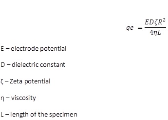
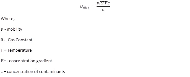
When we apply electric field during remediation, the positively charged water molecules will move towards the negatively charged cathode. As the cations move toward the negatively charged electrode, a shearing action takes place. The cations move through the pore water at high velocities and pull the water molecules along with them. This results in the large transfer of water from anode to cathode (Jane E. Apatoczky, 1992). The water molecules movement in the double layer is affected by Zeta potential which is actually the potential that develops between moving and stationary parts of Double layer around soil particles. The potential usually is negative and ranges between -10 to -100mV for saturated silts and clays. The flow would be reversed if the zeta potential is positive and this can happen if the contaminant concentration is high enough. In electroosmosis, flow depends on temperature, ion concentration, viscosity of pore water, dielectric constant and ion mobility. It is denoted as:
Electromigration
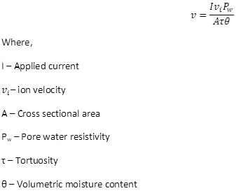
This is the motion of ions towards the electrodes as shown in figure 2. This transport mechanism is comparatively faster than the advective transport of electroosmosis and is the dominant transport mechanism during remediation. The rate of movement of ions is a function of ionic mobility, valence numbers and electrolyte concentration (Virkutyt., 2002; Sharma and Reddy., 2004). The ions travel with a velocity given by:
Electrophoresis
This is the movement of colloids towards electrodes and is similar to electromigration (Virkutyt., 2002). This type of movement is insignificant if the soil is tightly packed which would physically restrict the colloids from moving.
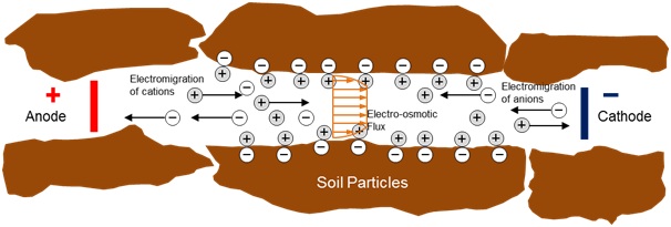
Figure 2: Transportation of ions in the soil (Cameselle et al., 2013)
The other electrokinetic mechanisms that occur during remediation include transportation due to streaming potential. The streaming potential develops when electrolyte is driven by pressure gradient through pores with charged walls.
Physical and Chemical Processes Involved
The physical and chemical processes involved are electrolysis, diffusion, adsorption-desorption, precipitation-dissolution and oxidation-reduction.
Electrolysis
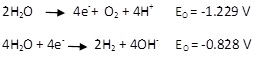
This is the reaction that occurs at the anode and cathode when an electric field is applied. In the case of electrokinetic remediation, water decomposition occurs at the electrodes. Oxidation takes place at the anode and hydrogen ions H+ and oxygen gas are generated. Reduction reaction takes place near cathode and hydroxyl ions OH- and hydrogen gas are generated. These are shown by the following equations (Cameselle et al., 2013; Sharma and Reddy., 2004).
The process of electrolysis leads to changes in the soil pH near the electrodes. The region near anode develops a low pH of about 2 wheareas near the cathode it increases up to 11 or 12. The hydrogen and hydroxyl ions move both due to electromigration and diffusion. The hydrogen ions being smaller than the hydroxyl ions tend to travel faster leading to rapid acid front migration at almost twice the speed of the base front migration. The acid front migration is even easier in low buffering capacity soils compared to high buffering capacity soils since the hydrogen ions get consumed to neutralize soil constituents (Sharma and Reddy., 2004). The acid dissolves the usual cations in the soil or precipitates and helps cation removal. If the contaminants are anionic, the acid front would increase adsorption and reduce contaminant removal. Both the acid and base front will in turn have an effect on the zeta potential of the soil influencing the flow.
Diffusion
Diffusion is the process where the contaminants move due to difference in concentration gradient. This usually does not contribute to a significant amount of contaminant transport in remediation. This depends on the tortuosity and porosity of the medium and the concentration of the species (Sharma and Reddy., 2004). The rate of diffusion is given by:
Adsorption-Desorption
Adsorption involves the movement of contaminants from pore water to the soil particles. Generally soils are negatively charged but it would depend on the pH of the soil (Reddy., 2011). The net charge in soil will be zero for a particular value of pH and that is called the point of zero charge (PZC). If the pore water falls to a pH less than PZC then adsorption of anions will be predominant and when pH rises above PZC the adsorption of cations are significant. Thus adsorption is dependent on factors including soil type, soil charge, contaminant, organic matter and pore water characteristics.
Desorption is the reverse of adsorption and involves the transport of contaminants from soil to pore water. When pH falls below PZC desorption of cations are significant and vice versa. Due to extreme pH differences between the regions near the electrodes, the cationic absorption and anionic desorption occurs near cathode. The anionic adsorption and cationic desorption occurs near anode. The area of the PZC is known as the slippage plane and beyond this, free porewater is present in the soil.
Precipitation-dissolution
Precipitation is the formation of solid that results when the concentration of compound exceeds its solubility. Dissolution is the reverse where compound forms a solution. Both processes are highly pH dependent and would occur depending on their location. The contaminants could be precipitated or dissolved during remediation. The dissolved contaminants would be easier to remove than the precipitated contaminants in soil.
Oxidation-Reduction
Redox reactions take place during the remediation process. Area near Anode experiences oxidation since electrons are lost and the cathode area experiences reduction since there is addition of electrons. Some metal cations precipitate near cathode. The valence of the metal ions decides on their solubility and thus might impact removal (Sharma and Reddy., 2004).
Applicability of Electrokinetic Remediation
Electrokinetic Remediation can be implemented for the remediation of soils, sediments and any porous material. This technique is used on both saturated and unsaturated soils though it works better on saturated soils. It can also be implemented on heterogeneous soils and used to treat a wide range of contaminants (Acar et al., 1995). The method is very effective in removal of strontium and cesium from high water content soil (Jane E. Apatoczky, 1992). pH control at the electrodes and the use of enhancement agents would broaden the range of contaminants that can be treated with this process such as lead, mercury and cobalt (Kornilovich et al., 2005). Thus, Electrokinetic remediation is a developing technology which intends to separate and extract radionuclides, heavy metals and organic contaminants from saturated or unsaturated soils, sludges, sediments and groundwater.
Advantages
The in-situ method is preferred since it would be less expensive. The process can target a specific area since the remediation will take place only between the electrodes. The fact that the soil need not be removed indicates that the amount of energy needed for this process would be comparatively lower than ex-situ procedures.
The technique is applicable for a wide range of contaminants since metal contaminants can be moved because they have charge and the non-charged contaminants are moved due to induced flow. It is flexible to be used as both in-situ and ex-situ method (Sharma and Reddy., 2004) and it can be tailored to site specific conditions.
Disadvantages
Electrokinetic Remediation could prove to be a time consuming process. Buried metal objects may prove to be a big challenge to this type of remediation since the current flow would get diverted. Another limitation to using electrokinetic remediation would arise if large amounts of non-targeted contaminants are present. For example, if the targeted chromate concentration is 0.0001% only in the soil whereas the chloride ions (if sea water was present in the site) are present in higher percentages, then the current would be carried by the chloride (due to the sodium chloride in sea water), removing the chloride ions preferentially from the soil and not the chromate ions.
The electrolysis reactions near the electrodes change the soil pH. Acidic conditions near anode will cause decay and degradation of the electrolyte. There could be stagnant zones between electrodes where the migration is very slow (Sharma and Reddy., 2004). In case any VOCs are present they would increase the soil vapor concentration during remediation. A study of electrokinetic remediation applied to diesel contaminated soils was conducted. This study showed that a month after remediation the pH of soil near anode was very low about 3.5 and was very high near cathode with a value of 10.8 (Kim et al., 2010). This seemed to have an adverse effect on the microbial community in the soils though the soil was remediated.
Field setup and Implementation
The field set up requires electrodes, power supply for supplying DC, wells, pumps and treatment units. The usually used electrodes are carbon, graphite, or platinum since they are inert and would not react in the process creating more contamination. The power supply is expected to deliver 1 A/sq. ft power between the electrodes. The power required to treat a cubic yard varies from 50 to 250 kWh. Ceramic wells are preferred to avoid corrosion during the process (Sharma and Reddy., 2004). Pumps are needed to remove the contaminated water from the wells. Treatment units are necessary to treat the contaminated water.
To make the remediation process cost effective the lowest possible voltage is used to meet the cleanup criteria. Field and pilot studies indicate that the voltage typically varies between 100 and 600 V and 15 and 50 A. the cost effectiveness also depends on the number of wells. Usual distances between the electrodes are 2 to 7 ft. It is sometimes ineffective in removing metals like mercury. This is due to the complex chemistry of the metal which does not allow it to be in solution as the soil chemistry changes (oxidation or reduction states) with remediation. Therefore for metals like mercury there is a need for enhancement methods to increase their solubility for successful removal and decontamination (Kornilovich et al., 2005). There are inexpensive ways to improve electrokinetic transport and chemical enhancement is one method. Enhancement solutions are used since the remediation causes premature precipitation. Ethylenediaminetetraacetic acid (EDTA), citrate and carbonate salts, sodium chloride and citric acids are used.
Upon completion of the installation system, the voltage is applied and enhancement solutions are introduced. The reservoirs are monitored to check for removal efficiency. The point where the system stops removal indicates the process is complete. In case the system no longer removes contaminant and still the target concentrations are not met then adjustments are made to the system. Electrode spacing can be decreased, more enhancement solution added or voltage can be increased.
The water near anode might get depleted since most contaminants move towards the cathode (Wieczorek,S., 2005). This could be overcome by replenishing the porewater adjacent to anode casing but never fully saturating it. Too much saturation might lead to extensive contamination in the soil resulting in more damage.
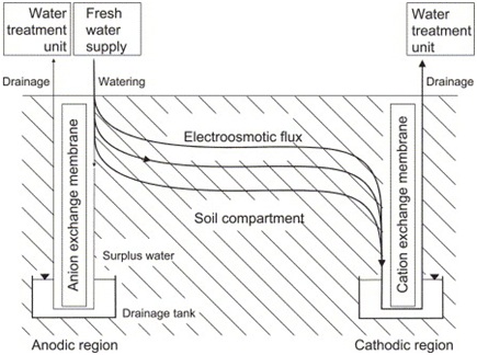
Figure 3: Water flux components during electrokinetic remediation in unsaturated soil (Wieczorek,S., 2005)
Similar Technologies for Soil Remediation
The Electrical Resistive Heating Remediation (ERH) is a technology where the Direct current is replaced by Alternating current. The arrangement is very similar to Electrokinetic remediation but this method does not depend on the transport of contaminants and instead depends on heating of the soil. This would be more effective in unsaturated soils for the removal of volatile organic compounds (US EPA. 1997). The contaminants are collected as soil vapors. This method is not recommended for saturated soils.
A recently improved technology is the Electrokinetically enhanced bioremediation. This process involves supplying the much needed nutrients, heat and water for the microorganisms so that they can carry out the contaminant degradation faster (Sharma and Reddy., 2004).
Another type of remediation involving electrokinetics is Electro-heated dual-phase extraction. This utilizes the heat produced during electrokinetics to volatlize some of the contaminants from the water that are pumped out near the electrodes (Sharma and Reddy., 2004).This technique is coupled with soil vapor extraction and groundwater extraction for removal of contaminants.
Economic and Regulatory Considerations
The cost involved in practicing this method is highly dependent on various factors of chemical and hydraulic properties of the soil. In the case of heavy metal remediation the energy consumption is estimated to be 500 kWh/m3 in pilot-scale studies when the electrodes are 1 -1.5m apart. The cost could vary between $25 - $225 per cubic yard depending on the target contamination, pore water conductivity and soil characteristics. The cost is also site-specific. The remediation process would alter the soil pH and metals might precipitate near the cathode (Sharma and Reddy., 2004). Though research has been conducted to avoid premature precipitation, there should be more research done to actually find a way to avoid the precipitation. More field studies would help in validating the migration rates by modeling.
The regulatory concerns here include time taken for the cleanup process since the efficiency decreases with time. The remediated site and the surrounding areas may not be able to sustain vegetation due to radical changes in the soil chemistry. Acid and basic fronts would remain in soil for a long time after the remediation is completed. Usually the soil near the cathode is removed since precipitation of the contaminants occurs.
CASE STUDY 1: U.S Department of Energy Paducah Gaseous Diffusion Plant, Paducah, Kentucky
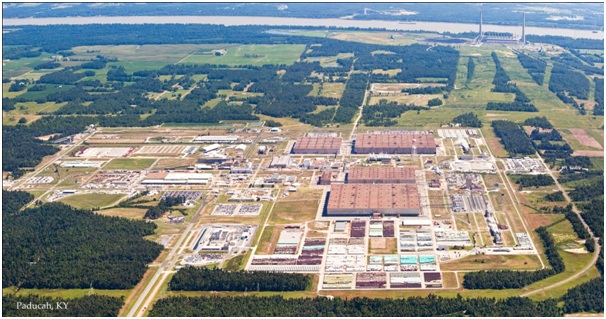
Figure 4: Paducah, KY (U.S Department of Energy)
Site History
The Paducah plant is located 3 miles south of Ohio River and 12 miles west of Paducah, KY. The plant was involved with the first nuclear weapons program in the United States. In 1952 they began enriching of Uranium for commercial power plants in the nation. The plant ran continuously and remained the only gaseous diffusion uranium enrichment plant in the U.S (DeGarady and Halbrook., 2003; Sharma and Reddy., 2004). The plant was owned by the U.S Department of energy (DOE) and managed mostly by the Kentucky Department of Fish and Wildlife. Their total area encompassed 3,556 acres of reservation and about 750 acres were used for the plant facilities. DOE leased the Paducah processing facilities for Uranium Enrichment to the United States Enrichment Corporation. The plant supported more than 50 years of uranium enrichment leading to a huge amount of hazardous, radioactive and non-chemical sanitary waste in the site. The soil, ground and surface water got contaminated.
Site Missions at Present
DOE has cleanup missions including environmental cleanup, waste disposition, decontamination and decommissioning (D&D) of the site, conversion of depleted uranium and long-term monitoring. DOE leases the plant to USEC which has been privatized and now the Nuclear Regulatory Commission regulates the site.
Electrokinetic remediation along with other in-situ methods is employed at this site. The soil at this site has very low permeability and the contaminants involved were TCE (Trichloroethylene). The field test work started in January 1995 and ended only in May 1995. The field experiment served as a pilot study to see the electrokinetic effects.
Remediation
The site consisted of 4 feet gravel and clay layers over 40 feet of sandy clay loam with interbedded sand layers. The hydraulic conductivity of the sandy clay was about 10-7 cm/s. The test area consisted of 150 sq ft area for a depth of 15 ft. Average contaminant concentration was 83.2 ppm. In this site, steel panels were used as electrodes and granular activated carbon was used to capture the contaminants as they moved towards the electrodes. The area was split into 4 treatment zones with 2 electrodes 10 ft apart. The treatment zones consisted of granular activated carbon in a staggered arrangement as shown in Figure 4. The electrodes had eight steel panels installed next to each other with a gap of half-inch. Each panel was 16 ft long and 18 inches wide. Fluid was circulated with tubes and pumps. A collection system was designed above the soil to collect vapors containing TCE. The test area was subjected to 40A and an initial power of 138 V for the first month. Then the voltage was reduced to 105 V. The average elecroosmotic flow was 4 to 5 L/hour. The temperature of the soil started increasing from 15oC to 30oC due to the applied electric field. The voltage gradient varied between 0.35 - 0.45 V/cm. the removal efficiency was promising since it was around 98%. The level of contamination fell to 1.2 ppm. The TCE concentration in the carbon treatment zones were high and were replaced. The cost for complete remediation in this test was $1310 per cubic yard. The electroosmosis flushes TCE from clay since this clay did not absorb much TCE and allowed the contaminant to move with the flow (Sharma & Reddy., 2004).
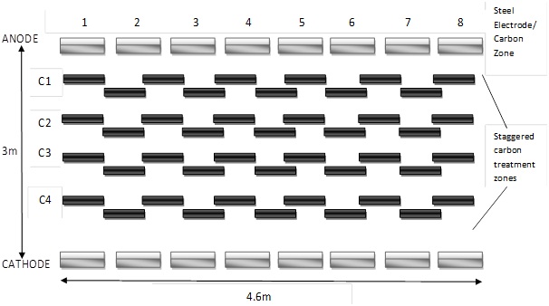
Figure 4: Schematic Representation of the Electrodes and the Carbon treatment zones (Sharma and Reddy., 2004)
Following the success of the small field test, a large scale remediation was carried out from August 1996 to March 1997. The soil type was the same as the small test field site. The test area had a larger size of 620 sq. ft. and a depth of 45 feet. The groundwater table started at 30 to 40 ft below ground surface. The electrodes were 1.5 in thick consisting of equal volume of iron filings and Loresco coke and were inserted to a depth of 45 feet. The electrodes were 21 ft apart. The iron filings help in promoting iron corrosion thereby reducing the hydrogen ion formation which occurs due to electrolysis. The area was split into 3 treatment zones and was a mix of Kaolin clay and iron filings. This setup was run with a constant voltage of 150 V. As high concentrations of TCE started showing up, the voltage was increased to a 200 V but this led to heating up of the soils and the voltage had to be brought down to 120 V.
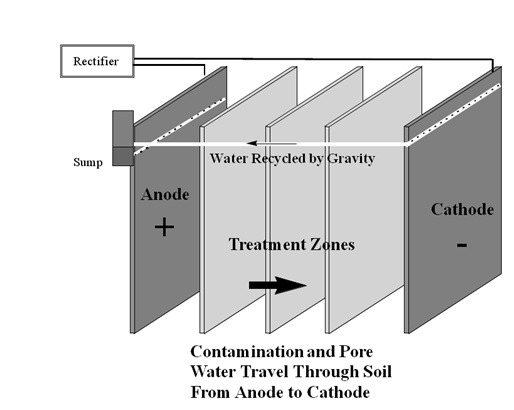
Figure 5: Contaminant and Pore Water Transport in Remediation process (Terran Corporation; Sharma & Reddy., 2004)
Results
The voltage gradient was 0.25 V/cm and it moved the water at a speed of 0.43 cm/day. The overall efficiency of the technique was 99.7%. TCE which existed in free phase in the site was believed to be removed in the same phase. The emissions were insignificant and the complete cost for this remediation was about $80 per cubic yard for a quarter of an acre at a depth of 45 feet.
CASE STUDY 2: Quicrez Industrial Site in Fond du Lac, Wisconsin
About the Site
The site consisted of high levels of TCE which also extended under the river bed nearby. The soil was saturated clay and silt with extremely high levels of TCE [DNAPL levels of TCE]. The site under treatment extended all the way to allow decontamination of half of the Fond du Lac River. Before the treatment was started the soil was sampled and substantial DNAPL was discovered which was found to be higher than the amount estimated during the initial design phase. Some of the areas had concentrations higher than 1000 mg/kg.
Remediation
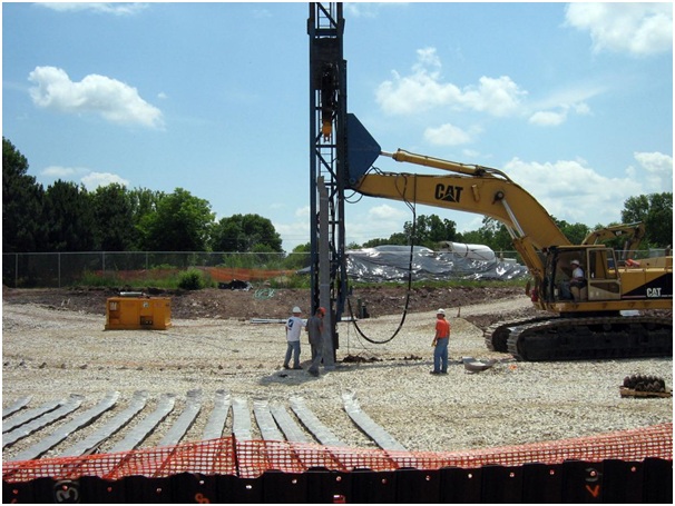
Figure 6: Electrode installation at the site. (Terran Corporation)
The remediation was started with two anodes and one cathode. The installations took just 3 weeks with the electrical and recycle plumbing taking 2 more weeks to be completed. The system was exposed to 208 V initially. The initial DC output measured somewhere around 190 and 500 A. Once the site started heating up to the operating temperatures of around 50oC, the power was reduced to 110 V and 450 A. Monitoring for this site was done remotely thereby saving some operational costs. The entire project lasted over 2 years till 2008 (Terran Corp.). The economic conditions of the state by then started deteriorating and hence the funding for this site was eliminated in 2009.
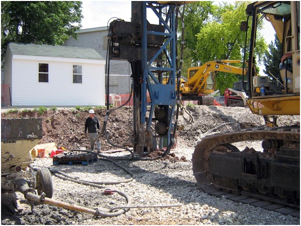
Figure 7: Installation of treatment zones in front of rectifier building. (Terran Corporation)
Results
After the funding was stopped, the post treatment sampling showed significantly lesser DNAPL concentrations. If the treatment had continued for some more time it would have been possible to reach the target contaminant levels. More than two thirds of the total TCE was removed and the zones of DNAPL diminished. The iron filings are still existent and continue to contain any TCE that might migrate across by diffusion or convection for years to come.
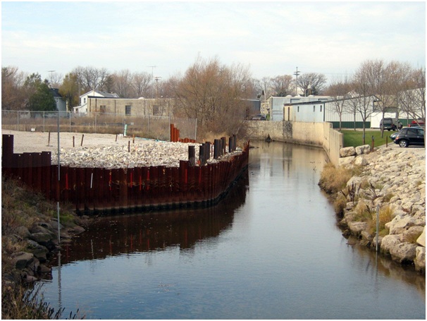
Figure 8: Completed Remediation of Quicfrez site and river terrace. (Terran Corporation)
CASE STUDY 3: Naval Air Weapons Station (NAWS) Point Mugu, California
Site History
The NAWS located in Ventura County, California, was chosen for demonstrating electrokinetic remediation. The site was under study and the area had been used for electroplating and metal finishing operations. The area of the site was approximately half an acre including two former waste lagoons located in the center. These lagoons are unlined and were in use between 1947 and 1978 when it received wastewater from the electroplating and metal finishing plants. The plating shop discharged about 95 million gallons of plating rinse solution and some organic solvents into the lagoons. In addition to this, the lagoons were also the dumpsite for 60,000 gallons of waste photographic fixer solution and rocket fuel (USAEC. July 2000). In 1994 an emergency removal action was decided and the surface samples from the lagoons showed high levels of Cadmium and Chromium (25,100 mg/kg and 1810 mg/kg respectively) far exceeding the allowable standards (2,500 mg/kg and 10 mg/kg respectively) of California.
Remediation
Before starting the remediation process, many laboratory tests were conducted with the soil samples from the site. These included testing for contaminant and soil characteristics, grain size distribution analysis, pH, Total Organic Carbon (TOC), Toxicity Characteristic Leaching Procedure (TCLP), Cation exchange capacity and hydraulic conductivity. These tests were followed by determination of electrode placement, migration rates, electrolyte requirements, removal efficiency and power requirements. This initial laboratory study was conducted by ERDC and Lynntech, Inc. and showed that the method can be successfully implemented at the site for remediation. The major method of contaminant transport was expected to be electromigration. (USAEC. July 2000)
System Setup
The setup consists of an array of cathodes and anodes as shown in the figure 9.
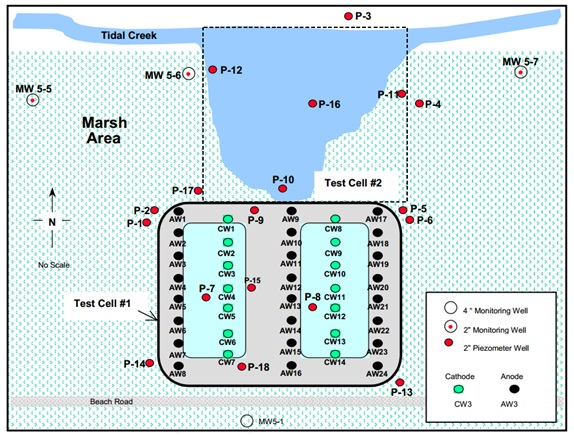
Figure 9: Schematic showing electrode wells (USAEC. July 2000)
The anode wells are 4 inch diameter with slotted PVC casings. They are wrapped in a linen fabric woven tight. The well is also packed with Kaolinite and sand. The cathodes are 3 inch diameter each with porous ceramic walls. These were designed by Lynntech (USAEC. July 2000).
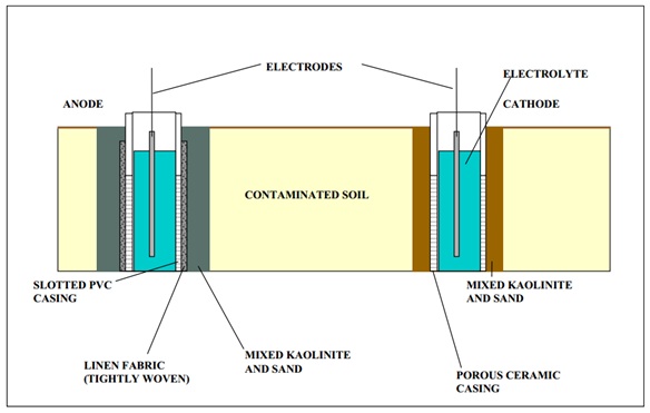
Figure 10: Electrode well Construction (USAEC. July 2000)
The site was subjected to 30 V and 333 A for remediation. Continuous monitoring was performed to check for soil heating. The sensors attached to each cell monitored temperature, pH, Voltage and current. Due to public and regulatory concerns mineral acids, nitric and sulphuric acids were not used in the site. Only citric acid was used for enhancement since it was available readily, environmentally friendly and was relatively inexpensive.
Decontamination Issues in the site
The site had sodium chloride presence and this led to production of chlorine gas along with oxygen at the anode wells. This required additional off-gas treatment in the design system. In addition to this, the metal sulphides present in the site led to the production of Hydrogen sulphide gas at the cathode wells. A scrubber system was introduced to treat the gas and it reacted with Sodium hydroxide. To increase chlorine gas removal efficiency, an air sparging system was installed.
After 22 weeks, low concentration of contaminants were discovered in some areas. But the progress review showed that some factors were retarding the remediation progress. Further inestigation was needed before implementation on a full scale basis could be considered and the field demonstration was suspended in 1998 October (USAEC. July 2000).
Results
After extensive evaluation, it was concluded that the bench scale tests did not accurately reflect the effects that would occur due to the remediation process. This was specifically true with respect to the competing ions having a retarding effect on the pH front development and contaminant transport. The bench tests also could not predict the efficiency or the duration accurately. The performance goals was to bring down the contaminants to California State regulatory levels but no contaminant was extracted during this process and samples were not collected after treatment. Hence the target levels were not met (USAEC. July 2000). The transport of electrokinetically mobilized contaminants within confined and unconfined areas were not assessed since the performance was poor during the demonstration. The technology had an adverse effect on the organic contaminants of the soil since they showed an increase.
Observation
The VOC data indicated an increase of vinyl chloride in some wells. This increase in contamination was mainly due to the dehalogenation process of PCE and TCE during electrokinetic remediation (USAEC. July 2000). The site characteristic that was primarily responsible for the poor performance of the remediation treatment was the presence of high chloride concentration in the soil. The chloride ions retard the development of pH front and in turn slow down the process of contaminant transport towards electrodes. The site conditions thus proved to be disadvantageous for electrokinetic remediation.
CASE STUDY 4: Creek bed, U.S Army Firing Range, Louisiana
About the Site
The creek bed in U.S Army firing range in Louisiana was contaminated with lead. Lead poisoning occurs due to the accumulation of lead in body tissues. Prolonged exposure will lead to digestive problems, neurological problems, high blood pressure and kidney dysfunction (US EPA, 2001). In 1996, the Department of Defense supported the Small Business Innovative Research Program in Collaboration with WES, Electrokinetics, Inc. in carrying out a comprehensive study on the lead contaminated site. U.S EPA takes part in the result assessment from the study. The soils are contaminated with very high levels of lead and it reaches almost 4,500 mg/kg in some areas.
The table shows the Lead classification according to the contamination levels in ppm of soil.
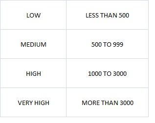
Table 1: Classification of Lead Levels in Soils (University of Massachusetts, 1985)
Remediation and Results
A pilot-scale laboratory testing was done for the removal of 2000 mg/kg of lead from the kaolinite in 1993. The electrodes were placed one inch apart in the soil. The total soil specimen volume was about two tons and the process was carried out for four months. The total energy cost reached about $15 per ton. At the site of the study, Electrokinetics, Inc. was using CADEXTM electrode system that would promote contaminant transport to the cathode compartment. The contaminants are precipitated or deposited directly (US EPA, 1997).
The removal efficiency was observed to be varying between 90 to 95%. The pilot scale studies showed that the lead concentrations decreased to less than 300 mg/kg within 30 weeks of processing. The toxicity leaching characteristic [TCLP] values dropped more than 300 mg/L to less than 40 mg/L within the same 30 weeks (US EPA, 1995).
Depending on soil type, the lead removal would vary. If the soil contains high amounts of Calcium or Magnesium then Lead is precipitated in groundwater and this would impact removal. Clays tend to show high bonding capacity and they slow the movement of contaminants. On the other hand, in clean silica or gravel, most of the minerals are removed and lead travels over longer distances easily (US EPA, 2001).
The results at the site are promising so far but full-scale efficiency or cost effectiveness have not been evaluated yet.
Recommended Reading
- Chinthamreddy, S., (1999). Geochemical characterization and enhanced mobilization of heavy metals during electrokinetic remediation of soils. University of Illinois at Chicago.
- Khire, M. V., Alshawabkeh, A. N., Reddy, K. R.,. (2008). "Geotechnics of waste management and remediation: proceedings of sessions of Geocongress 2008, March 9-12, 2008 New Orleans, Louisiana, sponsored by the Geo-Institute of the American Society of Civil Engineers." Order title:Geotechnics of waste management and remediation proceedings of sessions of Geocongress 2008 sponsored by the geo-institute of the American Society of Civil Engineers March 9-12, 2008 New Orleans, Louisiana, American Society of Civil Engineers, Reston, Va., xviii, 856 p.
- Pacific Northwest Laboratory., (U.S.)., and United States. (1994). "In situ soil remediation using electrokinetics." Pacific Northwest National Laboratory (U.S.) ;distributed by the Office of Scientific and Technical Information, U.S. Dept. of Energy, Richland, Wash. :Oak Ridge, Tenn., 34 p.
- Reddy, K. R., Cameselle, C., (2009). Electrochemical remediation technologies for polluted soils, sediments and groundwater. Wiley, Hoboken, N.J.
- Sharma, H. D., and Reddy, K. R. (2004). Geoenvironmental engineering: site remediation, waste containment, and emerging waste management technologies. Wiley, Hoboken, N.J.
- United States.,. (1997). Development of an integrated, in-situ remediation technology Task 2--4, electrokinetic modeling. Topical report, September 26--May 25, 1996.United States. Dept. of Energy. Office of Environmental Restoration and Waste Management ;distributed by the Office of Scientific and Technical Information, U.S. Dept. of Energy, National Energy Technology Laboratory (U.S.), Washington, D.C :Oak Ridge, Tenn.
References
- Acar, Y. B., and Alshawabkeh, A. N. (1993). "Principles of electrokinetic remediation." Environ.Sci.Technol., 27(13), 2638.
- Acar, Y. B., Gale, R. J., Alshawabkeh, A. N., Marks, R. E., Puppala, S., Bricka, M., and Parker, R. (1995). "Electrokinetic remediation: Basics and technology status." J.Hazard.Mater., 40(2), 117.
- De Battisti, A., and Ferro, S. (2007). "Electrokinetic remediation." Electrochim.Acta, 52(10), 3345.
- DeGarady, C. J., and Halbrook, R. S. (2003). "Impacts from PCB Accumulation on Amphibians Inhabiting Streams Flowing from the Paducah Gaseous Diffusion Plant." Arch.Environ.Contam.Toxicol., 45(4), 525.
- Jane E. Apatoczky, January 1992. "The Chemical Enhancement of Electrokinetic Soil Decontamination". M.S Thesis, Lehigh University.
- Kim, S., Han, H., Lee, Y., Kim, C. W., and Yang, J. (2010). "Effect of electrokinetic remediation on indigenous microbial activity and community within diesel contaminated soil." Sci.Total Environ., 408(16), 3162.
- Kornilovich, B., Mishchuk, N., Abbruzzese, K., Pshinko, G., and Klishchenko, R. (2005). "Enhanced electrokinetic remediation of metals-contaminated clay." Colloids Surf.Physicochem.Eng.Aspects, 265(1), 114.
- Lageman, R., Clarke, R. L., and Pool, W. (2005). "Electro-reclamation, a versatile soil remediation solution." Eng.Geol., 77(3), 191.
- Li, S., Li, T., Li, G., Li, F., and Guo, S. (2012). "Enhanced electrokinetic remediation of chromium-contaminated soil using approaching anodes." Frontiers of Environmental Science & Engineering in China, 6(6), 869.
- Reddy, K. R., Darko-Kagya, K., and Al-Hamdan, A. Z. (2011). "Electrokinetic Remediation of Pentachlorophenol Contaminated Clay Soil." Water, Air, & Soil Pollution, 221(1), 35.
- Sharma, H. D., and Reddy, K. R. (2004). "Geoenvironmental engineering: site remediation, waste containment, and emerging waste management technologies". Wiley, Hoboken, N.J.
- US Army Environmental Center. July 2000, "In-Situ electrokinetic Remedition of Metal Contaminated Soils Technology Status Report". SFIM-AEC-ET-CR-99022.
- US Department of Energy. "Paducah gaseous Dissusion Plant".
- US EPA Office of Solid Waste and Emergency Response. 1997. "Ground Water issue". EPA/540/S-97/502.
- US EPA Office of Solid Waste and Emergency Response. 1995, April. "In-Situ Remediation Technology Status Report". EPA/542/K-94/007.
- US EPA Office of Research and Development. 1997, March 5, "Recent Developments for In-Situ Treatment of Metal Contaminated Soils".
- Virkutyte, J. (2002). "Electrokinetic treatment overview 2002, science of the total environment.".
 Vidhya Ramalingam
Industry News


Events

19th European Conference on Soil Mechanics and Geotechnical Engineering, Istanbul, Türkiye
The 10th International Congress on Environmental Geotechnics

11th European Conference on Numerical Methods in Geotechnical Engineering

1st International Conference on Sustainability in Geotechnical Engineering (ICSGE 2027)

International Symposium on Cone Penetration Testing (CPT'27)

Rocscience International Conference 2027: Geotechnics, Structures & Hydro in the Age of AI
IS-GI Lyon 2027: International Symposium on Ground Improvement
GeoMandu 2027, 11th AYGEC and 1st SACG: Mountain Geotechnics for Infrastructure Development

Colloque National sur la Géotechnique


10 COMMENTS
Colin Jones*
Mar, 22, 2013 Interesting project. A major problem is the delivery system. This can be achieved using electrokinetic geosynthetics (EKG). For information on these see www.electrokinetic.co.uk Vidhya Ramalingam
Apr, 21, 2013 Colin Jones,Thank you for your comments. It is interesting and nice to know about the delivery system using Electrokinetic Geosynthetics.
Thank you once again for visiting my webpage.
Edit Comment
Prof. D N Singh*
Mar, 27, 2013 Dear Vidhya,You have presented it very well. A few questions for you:
1. How much a small test setup would cost?
2. How would you avoid short-circuiting that might occur due to the presence of highly contaminated soils?
Best wishes!
DNS
Vidhya Ramalingam
Apr, 21, 2013 Dear professor D. N Singh,The issue of cost has been addressed in the topic “Economic and Regulatory Considerations” in the webpage. The short circuiting would prove to be an issue if the soil has buried metal objects and in that case the Electrokinetic Remediation can be carried out only after removing them or there would be a need to use a different remediation technique. In the presence of heavily contaminated soils, this technique can be coupled with soil flushing where surfactants or solvents are used as additives and then the soil can be remediated Electrokinetically. This would avoid the issue of short-circuiting.
Thank you for visiting my webpage and providing valuable comments.
Edit Comment
Victor Damasceno*
Mar, 29, 2013 Good job on summarizing the application. Below are some comments for your consideration are:1. Note that Electrokinetic Phenomena result from the coupling between electrical and hydraulic flows/gradients. The resulting phenomena are electroosmosis, streaming potential, electrophoresis, and migration (or sedimentation potential – electromigration falls under this category). Consider extending your literature review section on each phenomenon.
2. Note that electroosmosis (EO) is effective in clays due to the negatively charged particles; however, EO does not work well on silts and sands due to the lack of a net negative charge. Consider revising the first paragraph under “Electroosmosis”.
3. You discuss four transport mechanisms resulting from electrokinetic remediation. Please note that diffusion, though a transport mechanism, is not an electrokinetic phenomenon. Consider moving to the “Types of contaminant transport mechanisms” section
4. Consider proofreading the report – portions of the report read as if sentences were removed and punctuation was not adjusted accordingly.
Vidhya Ramalingam
Apr, 21, 2013 Victor Damasceno,The literature on different Electrokinetic processes involved has been updated. The section of “Electroosmosis” has been revised for more clarity. The section “Diffusion” has been moved from the other Electrokinetic phenomena. The report has been proofread and changes have been made where they are necessary.
Thank you for your review and valuable comments. This helps in improving the webpage.
Edit Comment
James Wang*
Apr, 01, 2013 Hi Vidhya, you've selected an interesting remediation technology for your project. A few comments below:1. Diffusion is not an EK-induced transport mechanism. You can consider move it to the section discussing physical-chemical fate-and-transport processes.
2. Note that you did not include citation for Virkutyt,Jurate(?) 2002.
3. Under the section of Adsorption-Desorption, the statements about cations movement and shearing action should be related to electroosmosis.
4. Under the section discussing Oxidation-Reduction, the statement of "Anode experiences oxidation since electrons are lost ...." is not precise enough. Chemicals will be oxidized at anode, but anode itself should not be oxidized.
5. Under the "Disadvantages" section, the statement of "... the pH near anode developed from 3.5 to 10.8 ..." was confusing and should be rephrased to clarify.
6. There were a few places in several case studies mentioning the operating temperatures became an issue. What were those temperatures?
7. The mentioning of cost data was good. Note that these cost data were still fairly project- and site-specific and could vary significantly.
Vidhya Ramalingam
Apr, 21, 2013 James Wang,The section on ‘Diffusion’ has been moved from the other Electrokinetic phenomena to “Physical and Chemical processes”. The citation for the reference (Virkutyt., 2002) have been updated. The statements about cations movement and shearing action have been moved to the “Electroosmosis” section of the webpage. The statement regarding the oxidation near Anode has been modified for clarification. The statements under “Disadvantages” have been modified and rephrased. The operating temperatures for this process have been included in ‘case studies’ one and two. The issue of cost has been addressed in the topic “Economic and Regulatory Considerations” in the webpage and it has been included that the cost is site-specific.
I would like to thank you for visiting my webpage and reviewing my work. Your comments are valuable for improving this webpage.
Edit Comment
Sally Simpson*
Apr, 05, 2013 Vidhya,congratulations on a very comprehensive review. I was wondering if, based on your review, laboratory testing is something that is done in projects, prior to field testing, or on the basis of site characterization, engineers assess the effectiveness of the technique directly in-situ. Thanks!
Vidhya Ramalingam
Apr, 21, 2013 Sally Simpson,The laboratory testing is done in some of the projects. In other projects the engineers assess the effectiveness directly in-site with small-scale field testing. It would depend on the site and the contaminants involved. From the available literature it can be noted that the laboratory studies may not always show a good indication of the remediation efficiency in an actual field setting.
Thank you for your review and useful comments.
Edit Comment