Soil Remediation Techniques: Examination of In Situ Chemical Oxidation
Contents [show]
- Introduction
- Background
- Chemical Process
- Site and Contaminant Compatibility
- Advantages of In Situ Chemical Oxidation Technique
- Disadvantages of In Situ Chemical Oxidation Technique
- Implementation Design
- Considerations and Regulatory Aspects
- Economic Aspects
- Case Studies
- Recommended Readings
- References
Introduction
In Situ Chemical Oxidation (ISCO) is the procedure in which a chemical oxidant is introduced into the site’s subsurface with the purpose of transforming groundwater or soil pollutants into safer species (Hueling & Pivetz, 2006). Through chemical oxidation the oxidation state of a substance is decreased by accepting an electron to oxidize the target species. The target species is then put in a oxidized state which can eliminate the toxicity of the original contaminant.
Figure 1 provides a simple example of an oxidation-reduction reaction where copper is being reduced by gaining electrons and Magnesium is being oxidized by giving its electrons to Copper. This redox reaction is what takes place in the field with the addition of an oxidant. The oxidant being introduced into the field would act as the Copper by accepting electrons from the contaminant which then oxidizes to a less harmful species. It should be noted that there is In Situ Chemical Reduction Technology available as well in which the chemical introduced would reduce the contaminant into a safer species.

Figure 1: Oxidation Example (Clark, 2013)
ISCO technology is appealing as this reaction takes place in the field without the direct removal of the contaminant from the soil or groundwater. The four major oxidants used for ISCO are permanganate, persulfate, hydrogen peroxide, and ozone (Watts & Teel, 2006). Site characterization is critical for using the proper oxidant and implementation method. A complete understanding of the soil properties, hydrogeology, and geochemistry is essential for successful remediation using ISCO technology. The main target of ISCO remediation techniques are organic chemicals (Hueling & Pivetz, 2006). ISCO is typically used where contaminant concentration is high and it is usually introduced to the contaminant by pumping the oxidant into wells in the contaminated area. Figure 2 depicts the process of injecting an oxidant into a contaminated area.

Figure 2: In Situ Oxidation Application (Groundsure 2005)
Bench-scale studies can be useful in selecting the appropriate ISCO technique to be used. Although these studies can offer valuable insight to technique feasibility, its limitations in relation to field-scale studies need to be recognized and its results heavily analyzed (Hueling & Pivetz, 2006). In addition, pilot-scale studies are used when a larger volume of soil or groundwater needs remediation (Hueling & Pivetz, 2006). These help with the design and implementation of the final full-scale ISCO application.
The response time associated with this methodology is dependent upon numerous factors from the contaminated area, such as homogeneity of the soil, hydraulic conductivity and soil characteristics, groundwater flow or water table, and the longevity of the specific oxidant being used. This can be on the order or a few months to several decades resulting from a combination of these factors.
A detailed assessment of ISCO performance evaluation and rebound is necessary during and after remediation is completed. Hence, monitoring plays an important role in the final remediation results.
Permitting is generally not extensive for ISCO deployment. Regulatory issues associated with ISCO include state or federal programs associated with underground injection control and air quality (Interstate Technology and Regulatory Council, 2005). Each oxidant has health and systems specific to each and should be treated as such. Some oxidants are more hazardous than others such as permanganate and persulfate dust. With ISCO technology, there is potential for uncontrolled exothermic reactions or migration of oxidants and/or contaminants (Interstate Technology and Regulatory Council, 2005).
Background
In Situ Oxidation is based on oxidation methods originating from drinking water and wastewater treatment as early as 1930. The development and use of ISCO to remediate contaminated soil is fairly young and stemmed from on site or ex situ treatment in reactor systems (Tsitonaki, 2008). Watts et al.(1990) recognized that “a large number of hazardous waste disposal and spill sites are characterized by surface soils contaminated with chemicals that are resistant to degradation” and an alternative to bioremediation needed to be studied ( Watts et al., 1990). The first reports discussing ISCO treatment were published in the 1990s and by the middle of the decade companies were already offering ISCO services (Watts & Teel, 2006).
The first of ISCO processes to be investigated in laboratory research and fully developed was catalyzed H2O2 propagations (CHP), also known as modified Fenton’s reagent. Next, use of ozone sparging and permanganate treatment became common, and in the early 2000s persulfate became another oxidant option for ISCO remediation (Watts & Teel, 2006). ISCO has become widely used in the US with permanganate leading as the most common oxidant used in application. Persulfate is emerging as a successful oxidant with increasing field applications and a variety of implementation approaches (Tsitonaki, 2008). In oxidative treatment systems, numerous reactions could potentially occur, including acid/base reactions, adsorption/desorption, dissolution, hydrolysis, ion exchange, oxidation/reduction, precipitation, etc (Hueling & Pivetz, 2006).
ISCO has been used to remediate thousands of hazardous waste sites in the United States and is considered the fastest growing subsurface remedial technology nowadays (Hueling & Pivetz, 2006). As for any other remediation approach, the following steps need to be followed: 1) Site characterization (soil and contaminants), 2) Risk assessment (present or potential, it will determine if site will be remediated or not) and lastly 3) Selection of effective remediation technique.
The following sections of this document will further discuss this soil and groundwater remediation technology.
Chemical Process
The previously mentioned ISCO technologies are developed through specific chemical processes. Following, this paper will discuss such processes as well as their respective advantages and limitations.
Catalyzed H2O2 Propagations (CHP)
The CHP process is based on the catalyzed decomposition of hydrogen peroxide by soluble iron, iron chelates, or iron minerals in order to produce strong oxidant hydroxyl radical (OH•) (through Fenton’s initiation reaction) and other reactive oxygen species as seen in the following reactions (Watts & Teel, 2006):
H2O2 + Fe2+→OH• + OH− + Fe3+ (1)
OH• + H2O2 → HO2• + H2O (2)
HO2• ↔ O2•−+ H+ (3)
+ H2O2 → ROH + OH• (4)
HO2•+ Fe2+→ HO2− + Fe3+ (5)
The hydroxyl radical is one of the strongest oxidants found in nature and it is the oxidant of interest in CHP (Watts & Teel, 2006). However, in addition to hydroxyl radical, CHP uses other species produced by subsequent chemical reactions of hydroxyl radical with hydrogen peroxide. Some of these species include superoxide anion (O2•−), perhydroxyl radical (HO2•), and hydroperoxide anion (HO2−) (Watts & Teel, 2006). As further discussed in site compatibility, CHP reactions producing these four species can degrade almost any organic contaminant.
The nature of catalyst, pH, and hydrogen peroxide concentration greatly impact the CHP process. Added soluble iron and iron chelates, as well as naturally present iron oxide minerals, usually act as catalyst in CHP reactions. Their effectiveness is directly related to pH as soluble iron and iron oxide minerals are most effective in acidic pH environments and iron chelates at neutral pH (Watts & Teel, 2006). It is common practice in the field to increase the hydrogen peroxide concentration in cases where treatment is unsuccessful. Such increment will lead to further propagation reactions (equations 1 through 5) which will produce more reactive oxygen species and increase the treatment effectiveness (Watts & Teel, 2006).
One of the advantages of CHP technology with respect to others is its capability to treat sorbed contaminants and DNAPLs (Watts & Teel, 2006). On the other hand, a significant limitation is the high rates of hydrogen peroxide decomposition in surface soils and subsurface which means a low oxidant stability (Watts & Teel, 2006).
Permanganate
Permanganate (MnO4-) is a highly oxidized form of manganese that serves as a selective chemical oxidant in ISCO treatments. Potassium permanganate and sodium permanganate are the two most common sources of the chemical used for ISCO. The water solubility of permanganate depends on the medium temperature, size of crystal, extent of agitation, and concentration (Watts & Teel, 2006). The following equation illustrates the chemical reaction involved in the use of permanganate as an ISCO technique (Hueling & Pivetz, 2006)
MnO4- + 4H+ + 3 e- → MnO2 + 2H2O (6)
Permanganate is highly reactive with alkanes; hence it is most commonly used to oxidize chlorinated ethenes (e.g. TCE and PCE). It is also effective in the treatment of dichloroethylene isomers, vinyl chloride, phenols, and some polyaromatic hydrocarbons (Watts & Teel, 2006). However, it is ineffective in oxidizing chloroalkanes, benzene, and other aromatic compounds with low degrees of ring activation. As Watts et al. (2006) share, the cation associated with the permanganate (sodium or potassium) does not have a big influence on its oxidizing capability, but the permanganate concentration does.
Potassium Permanganate is rapid and cost-effective when treating DNAPL source zones or zones of high residual contamination. It is also appropriate for sites where the physical disruption of soils is desirable.

Figure 3: Permanganate in Situ Oxidation Application (Hueling & Pivetz, 2006)
Ozone
Ozone (O3)is one of the strongest oxidants available for remediation and is unique to other ISCO processes in that it involves the application of a gas (ozone) and therefore a different design and operation than other oxidants. It is composed of dry air or O2 which is inputted into an ozone generator and charged with a high voltage or UV irradiation where O2 molecules can be split and react quickly to form O3. Due to the instability of ozone, this must be generated on site.
Ozone oxidation chemical reactions can be divided into two categories: direct oxidation and indirect oxidation as shown in Equations 7-16. Direct oxidation involves the oxidation of the targeted chemical by ozone in one reaction. Unlike indirect oxidation, it does not rely on the hydroxyl radical (OH•) for achieving targeted results. Indirect oxidation follows a pathway that includes chain-initiating reactions, chain-propagating reactions, and chain-terminating reactions. Indirect oxidation is a faster reaction than direct oxidation due to the formation of the hydroxyl radical which rapidly attack organic contaminants and breaks down their organic carbon-to-carbon bonds (Interstate Technology and Regulatory Council, 2005).
Direct Ozone Reaction
O3 + RC = CR → RCOCR + O2 (7)
Chain-Initiating Reactions
O3 + OH- → O2 + OH• (8)
O3 + H2O → O2 + 2OH• (in the presence of ultraviolet light) (9)
Chain-Propagating Reactions
OH• + 2H2O → HO2 • + OH- + 3H+ (10)
HO2 • → O2-• + H+ (11)
OH• + RH → R• + OH- (12)
R• + O3 + H2O → ROH + O2 + OH• (13)
Chain-Terminating Reactions
HO2 • + Fe2 + → O2 + H+ + Fe3+ (14)
HO2 • + Fe2 + → HO2- +Fe3+ (15)
Fe3 + + O2-• → Fe2 + + O2 (16)
There are two forms of in situ ozone application: vadose zone injection of ozone gas and ozone sparging below the water table (Interstate Technology and Regulatory Council, 2005). In situ ozone oxidation involves the injection of mixture of air and ozone gas directly into the unsaturated and/or saturated zones. Depending on the reactivity and concentration of reactants, temperature, and pH, the longevity of ozone in the environment and extent of contaminant oxidation will vary significantly. Introduction of the ozone to the contaminant is done via ozone sparging, a similar mechanism to air sparging.
Ozone sparging however, does not result in a uniform distribution, rather it results in the formation of a limited number of air channels in which the majority of the injected air is transported (Huling & Pivetz, 2006). For best results, air channels during sparging must be as close as possible to where mass transfer zones overlap each other for successful transport. Ozone sparging can be advantageous due to its ability to be easily transported in water with high diffusive transport rate, and can be given in large concentrations in the unsaturated zone versus the saturated zone (Huling & Pivetz, 2006).
Ozone is low in solubility, dependent on temperature, and does not leave a residual. Depending on the properties of the site being remediated, these characteristics should be highly considered when deciding if ozone is the proper oxidant (Derby, 2009).The transport of ozone in unsaturated porous media is impacted by the water content, organic matter in the soil, and metal oxides in the soil. The higher the water content, the quicker the transport. An increase in content of organics and metal oxides decrease the transport. It should be noted that it may volatilize organics and generate high levels of dissolved oxygen which can be problematic with groundwater. There is no safe breathing concentration for ozone with a permissible exposure limit of 0.1 ppmv and immediately dangerous to life or health value of 5 ppmv. Heavy safety measures therefore must be used (Derby, 2009). Figure 4 is provided for a generalized schematic of the application of ozone.
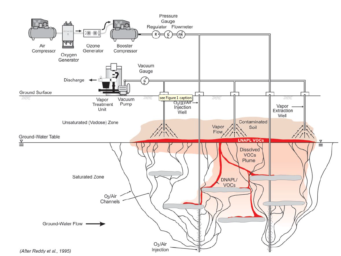
Figure 4: General conceptual model of in-situ ozonation in the saturated zone with soil vacuum extraction to capture volatile emissions and O3(g) (Huling & Pivetz, 2006).
Persulfate
The three persulfate salts most commonly used are ammonium persulfate, sodium persulfate, and potassium sulfate. Due to its solubility and content, sodium persulfate is the most widely used oxidant among them. Oxidation can occur via electron transfer or free-radical pathways. It is most common practice to activate persulfate to generate free radicals.
Na2S2O82- → S2O8 2- + 2Na+ (17)
S2O82- + activator→ SO4- + SO4- (or) SO42- (18)
Persulfate along with an activator to form sulfate radical for oxidation, SO42- , is favorable because the sulfate anion has a greater oxidation potential than the persulfate anion produced from Equation 17. The solubility of persulfate indicates that once injected, its transport mechanism will be dominated by density-driven and diffusive transport into low-permeability materials. It is more stable in the subsurface than other oxidants with a half-life of 100 to 500 days; this gives it the ability to be prominent in the system to further decontaminate an area for a longer duration. It has less affinity for natural organic matter than permanganate or peroxide and therefore less of it is needed. Unlike permanganate, it can oxidize benzene so it can be used in the remediation of fuels spills and benzene, toluene, ethylbenzene, and xylene contaminated groundwater. It is usually applied through direct injection or through horizontal or vertical recirculation wells. The powder must be mixed on site. Hydraulic fracturing can also be used if immediate response is required and there is low permeability layer. The density of persulfate increases with increasing concentration and therefore lower concentrations are needed for recirculation approach and higher for direct injection. Sodium Persulfate is more expensive than catalyzed hydrogen and permanganate. Safety considerations include that in powder form it is an irritant, corrosive and sulfate is a drinking water contaminant (Derby, 2009).
Site and Contaminant Compatibility
The appropriateness of ISCO technology is dependent on the effectiveness of, and ability to control the ISCO reaction with contaminants and the effective delivery of the reagents to the zone to be treated (Interstate Technology and Regulatory Cooperation Work Group, 2001). Depending on the choice of oxidant and site conditions, the natural oxidant demand can be several times the target compound oxidant demand.
Total Oxidant Demand = Target Compound Oxidant Demand (soil+water) +Natural Organic Oxidant Demand + Natural Inorganic Oxidant Demand (19)
When determining if a site is feasible for ISCO technology, careful site characterization and screening test should be performed. Specifically, test for hydraulic conductivity and test for heterogeneity within the contaminated zone should be undertaken. A hydraulic conductivity of greater than 10-7 cm/sec is recommended (Interstate Technology and Regulatory Council, 2005). This is important because lower hydraulic conductivity can cause pockets of untreated contaminants within the area being remediated. When applying liquid oxidants to the saturated and vadose zone, there is the potential to release contamination to the groundwater as the oxidant consumes organic matter in the soil. This is dependent on the permittivity of the soil (Interstate Technology and Regulatory Council, 2005). The greater the permittivity, the greater chance for the release of contaminants to the groundwater because the oxidant may not have had enough time to react with the contaminants (Interstate Technology and Regulatory Council, 2005). Table 1 outlines the specifications for site compatibility with each of the commonly used oxidants. Along with these specifications, the soil porosity, free product, and iron content should be evaluated. Free product must not be present because they limit the success of the oxidant. Iron and other heavy metals should be accounted for in the groundwater because they can interfere with the movement of the groundwater during remediation process (decrease in hydraulic conductivity).
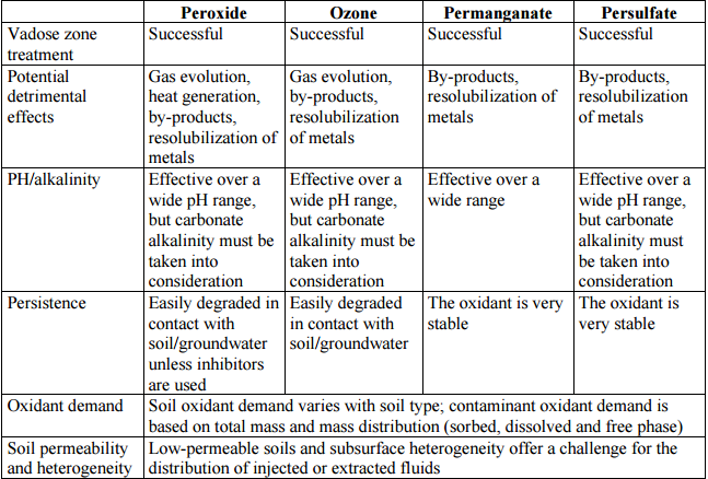
Table 1: Considerations for In Situ Treatment with ISCO (Interstate Technology and Regulatory Council, 2005)
As shown in Table 1, different oxidants are preferable for certain dominant characteristics of the soil. While these are all comparable for vadose zone treatment, they have different potential negative impacts as well as different levels of persistence.
Each of the previously mentioned processes have particular characteristics which could make them appropriate or not to use in a specific site cleanup. The appropriate process must be decided as product of site characterization (Table1) and investigation of the contaminants needing remediation (Table 2). The persistence of the oxidant in the subsurface is a crucial component because this affects the contact time for advective and diffusive transport and therefore the ability for the oxidant to oxidize the targeted components of the site subsurface being investigated (Huling & Pivetz, 2006).
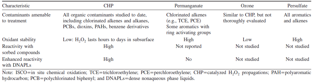
Table 2: Characteristics of major ISCO processes (Watts & Teel, 2006)
Advantages of In Situ Chemical Oxidation Technique
In situ chemical oxidation can be advantageous in multiple aspects dependending on the site being remediated. It can be applied to eliminate a wide variety of contaminants including aqueous, sorbed, and non-aqueous contaminants. Since this process is relatively fast and can occur in situ, it can be at a lower cost than other remedial technologies because there is no need for the removal of soil. ISCO has the ability to enhance mass transfer such as through heat from H2O2 reactions. This generated heat can increase reaction rates, and microbial activity and therefore efficiency. These characteristics make this method useful and highly advantageous for large areas.
Since ISCO does not generate large amounts of waste, this reduces contaminant exposure, time, and costs because disposal or treatment is minimal (Interstate Technology and Regulatory Council, 2005). ISCO technology is favorable over other remedial techniques in that it can be effective in treated Chlorinated Alkenes and chlorinated phenols, soil with low oxidant demand, and aerobic aquifers, all of which can be a problem for technologies requiring reducing conditions.
Disadvantages of In Situ Chemical Oxidation Technique
Disadvantages of this remediation technique include the potential of oxidant delivery problems if there is subsurface heterogeneity such as with the hydraulic conductivity of an aquifer. This issue could affect the transport of the oxidant so that it is not able to reach the full volume being treated. The subsurface layers and hydraulic conductivity of each must be clearly identified. There can be a short persistence of some oxidants due to fast reaction rates in the subsurface (Derby, 2009).
Although there is generally a lower lifetime cost, fast treatment requires spending a lot of capital quickly. If a contaminant is not fully treated or reduced to a less harmful species, it can be mobilized by transport induced by the oxidation (Derby, 2009). For oxidation to occur there must be a large redox potential which generally requires special safety requirements to handle these oxidants. There are limitations for application at heavily contaminated sites and you may have less oxidant or hydraulic control relative to other remedial technologies (Derby, 2009).
Mass transfer can be beneficial for increasing the active area of the oxidant but this can also further spread the contaminant from the area originally being remediated (Clark, 2013). Permeability could potentially be reduced as a result as well. Additional challenges to ISCO implementation include the presence of non-aqueous phase liquids or high concentrations of sorbed COCs, heterogeneous or low permeability soil, and current site conditions with sensitive utilities such as gas, steam, petroleum, communication lines, etc (Clark, 2013).
Implementation Design
To successfully reduce contaminants, the oxidant must come into contact with the contaminant molecules. As generally preferred, the distribution technique chosen should ensure that the oxidant is uniformly circulated throughout treated area (Interstate Technology and Regulatory Council, 2005).
In order to achieve adequate contact between oxidant and contaminate, the injected volume of the oxidant should represent an adequate fraction of the void space in the subsurface. If there is groundwater near, the volume used needs to be carefully determined (conservative) in order to not spread the contaminated groundwater beyond your site. The injection volume is largely dependent on the site-conditions and the type of oxidant being utilized. ISCO is typically used where contaminant concentration is high and it is usually introduced to the contaminant by pumping the oxidant into wells in the contaminated area. Common options include injecting into preexisting wells, specially installed wells, temporary direct push points, and permanant direct push wells (ITRC, 2001). These wells are installed at different depths in order to reach as much dissolved and undissolved contaminants as possible (USEPA 2012). Efficiency can be promoted by recirculating oxidants between wells so that the groundwater mixed with an oxidant is pumped out while more of the oxidant is pumped in through another well. Recirculation is especially useful for remediating large areas. This discussion will limit to describing application of the commonly used oxidants: permanganate, ozone, persulfate, and hydrogen peroxide (Interstate Technology and Regulatory Council, 2005). Implementation of these oxidants into the site requiring remediation is done in various stages which include a conceptual site model, bench-scale treatability testing, screening and selection of oxidant and delivery approach, pilot-scale testing, design development and full-scale implementation. The different methods for initiating this process are described as follows (City Chlor 2013).
Injection via Filters
As shown in Figures 5 and 6, the oxidant is injected into the soil with the use of pressure which requires vertical filters. It is rather simple to inject multiple rounds of injection but the cost of the material used in the injection filters can be high since the filter material should be resistant to the oxidants used.

Figure 5: Schematic View of Injection (City Chlor, 2013)
Figure 6: Schematic Side View of Injection (City Chlor, 2013)
Injection via Direct Push Methods
In this process the oxidant is injected into the soil via direct push methods. Direct Push Technology refers to the driving, pushing, or vibrating of small-diameter hollow steel rods into the ground. The oxidant can be inserted into this steel rod to be distributed as needed. The maximum depth, however, is limited to 20 meters. The shape and dimensions of the oxidant plume of one injection point depends on the injection rate, pressure, heterogeneity, permeability, and speed at which the oxidant is consumed. It is overall best to use pumps that can handle a rate of 20 liters/minute and a pressure of at least 1500 kPa for sandy soils to 5500 kPa for loam soils. The most important soil characteristic that determines the success of this method is permeability. The lower the permeability, the more difficult the injection will be.
This is relative simple to use to a certain depth but if a second round is needed, the cost can increase further because a new rod is needed. The radius of influence is slightly smaller than injection filters. This can be an advantage if you are treating according to the presence of contaminants. Direct push methods can be expensive if several injection rods are required (City Chlor 2013).
Figure 7: Example of protected-screen Direct Push well installation (Interstate Technology and Regulatory Council, 2006)
Recirculation
This method combines direct injection or infiltration and groundwater abstraction. As seen in Figure 3, the oxidant is injected into one well and the groundwater with the oxidant is pumped out another well at a specific distance away which is a function of its time to oxidize the contaminant. Through the process of infiltration and extraction, a larger hydraulic gradient is created within the contaminated area. This increase ensures that the remediation can take place faster than with only an injection system. This larger hydraulic gradient increases the area of influence (CityChlor 2013). This can be at a high cost but can minimize the amount of oxidant needed and for shorter time duration. This process can be very efficient if there is good hydrological control. Figure 8 shows a simpler schematic of the process.

Figure 8: Diagram of recirculation method used in ISCO treatments (Interstate Technology and Regulatory Council, 2005)
Infiltration
This method is implemented by infiltrating the oxidant passively through horizontal or vertical filters. This is only possible in highly permeable soils but can be adapted the specific conditions of the site with vertical filter configuration. Horizontal filters are less recommended if there are heterogeneities in the soil. In a passive system, the infiltration capacity of the soil, the groundwater level, groundwater flow rate, and life of oxidant must be accounted for. Figure 9 shows this processs.

Figure 9: Injection through passive Infiltration (City Chlor, 2013)
The infiltration capacity of the soil is heavily influenced by the soil type. The coarser the soil, the higher success of infiltration via filters. Infiltration tests should be performed before this. For indirect application, the groundwater flow should be greater than 0.05 m/day and if it is lower than passive treatment should be sufficient. Furthermore, the following conditions must be satisfied for infiltration via filters to be a reliable method (City Chlor 2013):
- The oxidant must remain reactive in the soil long enough to oxidize the contaminants
- The oxidant must remain stable long enough to create a sufficient large radius of influence
- The injection of an oxidant must not have harmful products to people or nature
Soil Mixing
In this technique, the contaminated soil is mixed with the oxidant with the use of auger drills which have a diameter of 1 - 3.5 meters. This creates excellent contact between the oxidant and contaminants but is limited to shallow soil (less than 2 meters in depth) and there is a loss of soil structure. As you increase in depth, the costs increase dramatically. The oxidant is applied by a dosing system in the auger.
Figure 10: Soil Mixing using In Situ Oxidation (Regenesis, 2015)
Sparging
This is the injection of ozone into the saturated zone. It is only applicable for ozone. These methods have been derived from conventional compressed air injection techniques and have more stringent requirements and require expensive material due to the corrosive nature of ozone. During this process, ozone is produced continuously. Pilot tests can be performed to determine the radius of influence.
The three application possibilities are as follow (City Chlor, 2013):
Injection Filters
- Microporous injection filter
- The air/ozone is injected into the soil in very small bubbles
- Able to spread a relatively great distance in the soil
Recirculation Well
- Two injection filters and an underwater pump
- Consists of 2 injection filters and an underwater pump
- The injection causes an upward flow of the injected gas which in correspondence with the pump, creates a circulation effect
- This results in a larger radius of influence
Perozone
- Combination of gas/liquid injection
- The injection filter is coated with glass beads where H2O2 is passed
- This results in a mixture of ozone and hydrogen peroxide which is injected in the soil
Considerations and Regulatory Aspects
The use of ISCO techniques includes safety and health issues which need to be addressed. As shared by the Interstate Technology and Regulatory Cooperation Work Group (2005), some of such issues include:
- Oxidants must be safely handled and stored
- Permanganate and persulfate dust is hazardous
- The presence of ozone increases the flammability of many materials
- The generation of ozone can involve high-voltage-equipment concerns
- There is a potential for uncontrolled exothermic reactions
- There is a potential for preferential migration of oxidants and/or contaminants (liquid or vapor) through underground utilities
In order to avoid health complications due to hazardous dust inhalation, those directly dealing with the oxidants (most susceptible to toxicity) need to take appropriate safety measures such as wearing respiratory, skin, and eye protection at all times and minimizing the creation of mist or dust (Interstate Technology and Regulatory Council, 2005). The potential for flammability can be reduced by controlling the rate of decomposition of the oxidant (e.g. using low concentration oxidants and controlling its application) and/or by acknowledging and controlling the chemicals with which the oxidant could react (Interstate Technology and Regulatory Council, 2005). Also, when dealing with sodium persulfate, it must be stored in cool, clean, dry places away from heat and moisture sources since excessive heat and moisture can lead to self-accelerating decomposition and further combustion in surrounding materials (Interstate Technology and Regulatory Council, 2005).
The injection of oxidants and reagents are generally regulated through the Underground Injection Control (UIC) program of the Safe Drinking Water Act (SDWA), the Resource Conservation and Recovery Act (RCRA), the Comprehensive Emergency Response, Compensation, and Liability Act (CERCLA), and the Emergency Planning and Community Right to Know Act (EPCRA) (Huling & Pivetz, 2006). Moreover, specific regulations and permits regarding ISCO techniques vary by state. A selection of permits needs to be issued prior to ISCO techniques applications. For instance, the state of New Jersey requires New Jersey Pollution Discharge Elimination System (NJPDES) Discharge to Ground Water (DGW) permits for any actual or potential discharge of pollutants to the ground, while Missouri and Texas require the completion of its “Form UIC-Application for Class V Permit” and the “TCEQ Class V Injection Well Inventory/Authorization Form” respectively (Interstate Technology and Regulatory Council, 2005). Overall, states require an extensive description of the problem and proposed remediation technique to provide permits.
Monitoring is required not only while conducting ISCO treatments but also after: process and performance monitoring and post-treatment and closure monitoring (Interstate Technology and Regulatory Council, 2005). As its name indicates the first type of monitoring takes place during the most active phase of the remediation practice. In such period of time, it is conducted frequently to ensure that the technique is working as intended. On the other hand, post-treatment and closure monitoring takes place on a more infrequent basis after the soil reaches equilibrium in order to verify cleanup results.
In order to determine the effectiveness of active soil and groundwater ISCO technique the following criteria are proposed by ITRC:
- Groundwater elevation contour maps
- Graphs of contaminant concentrations over time
- Summary of the volume of soil/groundwater treated
- Summary of contaminant concentrations above/below applicable remediation standards
Economic Aspects
The cost of using ISCO depends on various components including the site contaminant (type and concentration), treatment zone volume, subsurface heterogeneity (hydraulic conductivity), and the overall treatment goal (Remediation Technologies Screening Matrix and Reference Guide: Chemical Oxidation, 2006). Picture 11 shows a detailed cost estimate for implementation of ISCO technologies.
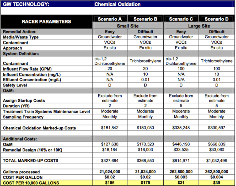
Figure 11: ISCO technology general cost (Remediation Technologies Screening Matrix and Reference Guide: Chemical Oxidation, 2006)
Case Studies
Case Study 1: Former Service Station Site; Southeastern PA
This project took place in Southeastern Pennsylvania (1999) and consisted of an out-of-service , former retail petroleum service property underlaid by a silty sand and fill material with a depth to groundwater table of approximately 10-12 feet (Interstate Technology and Regulatory Council, 2005). The site was underlid by soils and groundwater contaminated by LNAPL and high residual concentrations of petroleum hydrocarbons (BTEX, MTBE, and PATH (naphthalene)), and was very close to a large pet store which was one of the main receptors (Interstate Technology and Regulatory Council, 2005). Figure 12 shows the extent of contamination previous to site remediation.

Figure 12: Contamination extent before ISCO remediation (Interstate Technology and Regulatory Council, 2005)
The remedial design had as goal to remove all LNAPL from subsurface and to reduce hydrocarbons to levels at which natural attenuation could become a viable long-term approach to site cleanup (Interstate Technology and Regulatory Council, 2005). In situ oxidation via ozone sparging was used to remediate the site by the nine-month deadline. For eight months, ozone sparging was conducted through a series of six nested sparge points to reduce concentration of hydrocarbons in saturated and unsaturated soils and groundwater (Interstate Technology and Regulatory Council, 2005). Ozone sparging was complemented by soil vapor and groundwater extraction; the extracted and treated groundwater was then reinjected into the subsurface to further enhance remedial effectiveness (Interstate Technology and Regulatory Council, 2005).
In the months following culmination of the remediation process, several soil and groundwater samplings were conducted to corroborate effectiveness of technique. The resulting outcome was a decrease of 86%-99% in total BTEX, 97%-98% in total MTBE, and 52%-97% in total naphthalene across the site (Interstate Technology and Regulatory Council, 2005). Furthermore, groundwater concentrations also continued to decrease after the implemented remediation, demonstrating that natural attenuation was indeed taking place (Interstate Technology and Regulatory Council, 2005). LNAPL at the site was removed and concentrations were below the PADEP cleanup standards. The total costs for remediation accounted for approximately $222,000, including a two-year period of post-remediation sampling, reporting, and site closure negotiation with PADEP (Interstate Technology and Regulatory Council, 2005). Figure 13 illustrates the contamination extent after ISCO remediation.
Figure 13: Contamination extent after ISCO remediation (Interstate Technology and Regulatory Council, 2005)
Case Study 2: Anniston Army Depot, Anniston, AL
The project took place in Anniston, Alabama (1997) at a 2 acres site consisting of three industrial waste lagoons backfilled with clay in 1978 and with a water table fluctuating from 25-30 ft below the surface (EPA, 1998). The underlying lithography comprises over 43,125 yd. of contaminated soil containing up to 31% trichloroethene 3 (TCE), dichloroethene (DCE), methylene chloride, and benzene, toluene, ethylbenzene, and xylene (BTEX) (EPA, 1998). The majority of contaminants were found at depths of 8 ft and greater, while the highest concentrations of TCE are found at depths between 8 and 10 ft (maximum 20,100 mg/kg) (EPA, 1998). After fully characterizing the soil and contaminants present, hydrogen peroxide (H2O2) was chosen to remediate the site.
Three different types of injector wells were installed to target three distinct depth intervals (EPA, 1998):
- Single shallow injectors screened (8-14 ft deep) were installed where contamination was shallower than 15 ft
- Single intermediate injectors were installed where contamination was 15-20 ft deep
- Paired shallow and deep injectors screened (20-26 ft deep) were installed where contamination was at both deep and shallow depths.
Also, 25 deep ground-water injector wells were used for monitoring and a vent flow balance system was installed to aid in ensuring an effective radial dispersion of catalyst and H2O2. The Geo-Cleanse® patented injection process was used to distribute H2O2 and track quantities of ferrous sulfate and acid into the contaminated soil (EPA, 1998). Chemical oxidation of the soil took place over a 120-day period during which 109,000 gallons of 50% H2O2 were injected through a total of 255 injectors (EPA, 1998).
Results of the areas treated with H2O2 indicate that the remediation technique was effective in reducing contaminant concentrations in clays to below SSLs (EPA, 1998). Soil concentrations of up to 1,760 mg/kg of TCE have been reduced to below detection. The approximate total cost of the project is $5.7M (EPA, 1998).
Case Study 3: Cape Canaveral Air Force Station, FL
Cape Canaveral Air Force Station contains waste contaminants of discharge from rocket engines and parts. The cleaning compounds used to clean these rocket parts were part of the waste generated which included chlorinated solvents (TCE) (Federal Remediation Technologies Roundtable, 2006).
Permanganate was implemented at Launch Complex 34, Cape Canaveral Air Force Station to test the technology of ISCO with the objective of destroying TCE present as DNAPL in the saturated zone. The test zone volume was 75 ft by 50 ft by 45 ft deep. A total of 842,985 gallons of permanganate solution was injected into this plot in 3 phases over the span of 8 months. Figure 14 depicts the implementation process for this project.
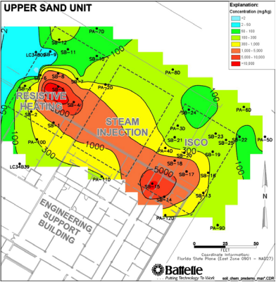
Figure 14: TCE Concentration before ISCO (Federal Remediation Technologies Roundtable, 2006)
During the first phase 304,763 gallons was injected into the order as follows: upper unit, middle unit, and the lower unit for one month. The radius of influence for the first injection was about 10-12 feet; however heterogeneities of the soil limited oxidant distribution. The second and third phases focused on targeting oxidation of areas which had not had sufficient levels of oxidant to produce satisfactory results, or the destruction of the contaminant. A total of 87,483 and 450,739 gallons were injected in the second and third phases respectively (Federal Remediation Technologies Roundtable, 2006).
Results showed (Federal Remediation Technologies Roundtable, 2006):
- Mass TCE and DNAPL levels decreased by 77% and 76% respectively and the topsoil demonstrated the highest levels of removal (indicating the oxidant was most efficient in coarser soils)
- Decreased TCE levels were consistent, with most monitoring wells displaying concentrations of less than 5 micrograms/liter which corresponds to the minimum concentration level
- TCE and DNAPL removal pathways included destruction by oxidation, migration to the surrounding aquifer, and migration to the vadose zone and atmosphere
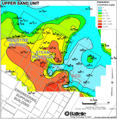
Figure 15: TCE Concentration after ISCO (Federal Remediation Technologies Roundtable, 2006)
The total cost of this project was about $1 million from design to finish. About 15% of this cost was estimated to be due to the fact this project was especially designed for demonstration purposes versus full scale applications (Federal Remediation Technologies Roundtable, 2006).
Recommended Readings
- Elisa Ferrarese, G. A. (2007). Remediation of PAH-contaminated sediments by chemical oxidation. Journal of Hazardous Materials.
- Siegrist, D. D. (1995). IN-SITU CHEMICAL OXIDATION OF TRICHLOROETHYLENE USING HYDROGEN PEROXIDE. JOURNAL OF ENVIRONMENTAL ENGINEERING.
- Susan H. Fergusona, A. Z. (2004). A field trial of in situ chemical oxidation to remediate long-term diesel contaminated Antarctic soil. S.H. Ferguson et al. / Cold Regions Science and Technology.
- Watts, P. K. (1997). DEPTH OF FENTON-LIKE OXIDATION IN REMEDIATION OF SURFACE SOIL. JOURNAL OF ENVIRONMENTAL ENGINEERING.
References
- City Chlor (2014). "In Situ Chemical Oxidation (ISCO)." In-situ-Verfahren Zur Boden- Und Grundwassersanierung HELD:IN-SITU-VERFAHREN ZUR BODEN- UND GRUNDWASSERSANIERUNG O-BK 357-94. City Chlor. City Chlor, 5 Apr. 2013. Web.
- Clark (2013). "Definitions of Oxidation and Reduction (redox)." Definitions of Oxidation and Reduction (redox). Chem Guide. Web. 11 Nov. 2015.
- Derby (2009). "In Situ Chemical Oxidation for Groundwater Remediation." SERDP/ESTCP Environmental Remediation Technology (2011). Environment. Groundwater and Environmental Services, Inc., Web.
- Environmental (2005). "Groundsure Blog." PersulfOx. Groundsure. Web. 11 Nov. 2015.
- Federal Remediation Technologies Roundtable (2006). “In Situ Chemical Oxidation (ISCO) Treatment of DNAPL Source Zone at Launch Complex 34, Cape Canaveral Air Force Station, Florida”. Federal Remediation Technologies Roundtable
- Huling &Pivetz (2006). "In Situ Chemical Oxidation." CIRP Encyclopedia of Production Engineering (2014): 469. Environmental Issue. United States Environmental Protection Agency. Web.
- James A. Jacobs, S. M. (2003). “Design Considerations for In-Situ Chemical Oxidation Using High Pressure Jetting Technology.” Soil Sediment and Water.
- Regenesis (2015). "Regenesis Remediation Services™ – PCE Treated with RegenOx® - REGENESIS Remediation Solutions." REGENESIS Remediation Solutions. N.p., Web. 12 Nov. 2015.
- The Interstate Technology and Regulatory Council (2001). "Technical and Regulatory Guidance for In Situ Chemical Oxidation of Contaminated Soil and Groundwater." IRTCWEB. The Interstate Technology and Regulatory Council. Web.
- The Interstate Technology and Regulatory Council (2005). "Technical Guideline." Dictionary Geotechnical Engineering/Wörterbuch GeoTechnik (2014): 1374. ITRCWEB. The Interstate Technology and Regulatory Council. Web.
- The Interstate Technology and Regulatory Council (2006). "The Use of Direct Push Well Technology for Long-term Environmental Monitoring in Groundwater Investigations." IRTCWEB. The Interstate Technology and Regulatory Council. Web.
- Tsitonaki, Environmental Engineer Ph.d. Aikaterini, Orbicon A/s, Professor Poul L. Bjerg, and Dtu Environment (2008). IN SITU CHEMICAL OXIDATION (n.d.): n. pag. ATV Jord Og Grundvand. ATV Jord Og Grundvand. Web.
- USEPA (2012). "In Situ Chemical Oxidation (ISCO) | REGENESIS." REGENESIS Remediation Solutions In Situ Chemical Oxidation Comments. USEPA. Web. 11 Nov. 2015.
- Watts et al. (1990) "Treatment of Pentachlorophenol-Contaminated Soils Using Fenton's Reagent." Hazardous Waste and Hazardous Materials
- Watts et al. (2006). "Treatment of Contaminated Soils and Groundwater Using ISCO." Practice Periodical of Hazardous, Toxic, and Radioactive Waste Management
 Brook Spruit
  Liana Lantigua Cuni
 Industry News


Rockfall Mitigation Project in West Virginia


Events
12th International Symposium on Field Monitoring in Geomechanics 2026

DFI 50th Anniversary Conference on Deep Foundations

9th International Symposium for Geotechnical Safety and Risk

5th International Symposium on Frontiers in Offshore Geotechnics (ISFOG)

Pan Mediterranean Geotechnical Engineering Conference

The Third Vietnam Symposium on Advances in Offshore Engineering

4th Asia-Pacific Conference on Physical Modelling in Geotechnics (ACPMG 2024)

The 2nd GeoMandu: Geotechnics for Sustainable Infrastructures

5th International Conference on Transportation Geotechnics


4 COMMENTS
Rachel McAllister*
Dec, 09, 2015 Thank you for a very thorough description of chemical oxidation. I think you did a great job. I was wondering if you have a feeling of which method for oxidation (as described in section 7) is most common? i.e., injection, recirculation, infiltration or mixing? Also, do you have a picture or schematic of injection via filters? What does it look like? Brook Spruit
Dec, 13, 2015 Dear Ms. McAllister,Thank you for taking the time to review our project. We appreciate the compliment as well as the helpful feedback.
We added a schematic for the method of injecting via filters, including a side view, in Section 7.1. For consistency, we found a schematic of passive infiltration as well for Section 7.4.
As for the most common implementation method of ISCO, we found injection through preexisting wells or direct-push methods to be the most common due to simplicity and the ability to reach depths as needed. We incorporated this into Section 7 as well.
Brooke and Liana
Edit Comment
Marina Pantazidou*
Dec, 10, 2015 I wonder whether there is a mix up between the technology you meant to describe and the technology you are actually describing.We add an oxidizing agent, or an oxidant, or an oxidizer, in order to oxidize the contaminant (electrons are removed/lost), while the oxidizing agent itself is reduced (electrons are added/gained).
To make an analogy with the example you give, Cu would be the oxidant and Mg the contaminant, which is being oxidized.
There is also the technology of In situ chemical reduction (ISCR), whereby we add a reducing agent, in order to reduce the contaminant (electrons are added/gained).
Brook Spruit
Dec, 13, 2015 Dear Ms. Pantaziou,Thank you for taking the time to review our project. Your comments and suggestions are very much appreciated.
After further review, we edited our introduction example to correspond to the right technology. We intended to state that Copper should be the oxidant as it is accepting electrons from Magnesium in order to oxidize it. Therefore, Copper would be the oxidant introduced into the field to take electrons from a hypothetical contaminant such as Magnesium to oxidize it into a safer species.
That is also interesting that ISCR is being used as well and we mentioned this in our report to inform that this similar technology is available as well.
Brooke and Liana
Edit Comment