End Uses of Landfills
Contents [show]
Introduction
Landfills pose a number of environmental and social issues while in operation which are regulated by USEPA, state governments, and local municipalities. However, the way the land is used after the landfill reaches its capacity is an important long-term consideration for the owners of the landfill and the communities surrounding them. As the population density in an area continues to increase, the value of reclaimed land occupied by landfills also increases. According the USEPA (2014), and as demonstrated in many case studies, the long-term end use of a landfill should be considered in the original design, or at least early in the life of the landfill. Poor planning can lead to costly redesign and extra work in terms of grading and drainage planning, cover design to support foundations, gas collection and control systems, settlement mitigation, and more. Thus, foresight on how the land will eventually be used can save project owners significant funds.
This paper introduces some of the most common end uses of landfills, discussing advantages and applicability of alternatives to different landfill sites and presents case studies emphasizing successes and challenges for post-closure end uses. Engineering considerations for topics discussed are presented to provide preliminary insight to what issues may be faced when choosing what to do with a landfill post-closure. The presentations of each topic in this paper are not comprehensive due to the unique nature of each landfill project. Case studies are helpful to look at because every landfill project is unique, so creative solutions are developed specific to each project. Some regulatory aspects of landfill management related to landfill gas and leachate are also discussed, but those issues are not the main focus of the paper. However, it is important to keep in mind that regardless of the end use of the landfill, standard post-closure requirements apply. This typically entails post-closure management of landfill gas and leachate control systems, and groundwater monitoring for a period of 30 years after site closure, per the Resource Conservation and Recovery Act (RCRA). However, the Interstate Technology and Regulatory Council (2006) offers guidelines for optimizing post-closure care on a performance basis, which can reduce the time period required for post-closure care. Either way, these systems must be integrated into the end use of the landfill in such a way as to protect the health and safety of people and the environment.
Recreational Uses
The most common end use for landfills is developing the land for recreational use. Examples of recreational uses are golf courses, nature parks, fields, and walking or biking trails for public use. These types of development are relatively easy to construct and maintain because differential settlements due to waste decomposition do not adversely affect recreational facilities like they do with buildings. However, settlement is still an issue that must be accounted for. Along with settlement and other issues ubiquitous to landfills, in any recreational end use design, capping, trees, and landscaping are critical features that must be designed and maintained carefully (Sharma and Reddy, 2004).
Settlement
Sharma and Reddy (2004) suggest that for recreational end uses, the issue of differential settlement is more important than average settlement. Differential settlement can adversely affect grades throughout the site, which are designed to achieve consistent drainage/runoff, by changing the direction of drainage or by ponding. Ponding is one consequence of differential settlement that is easy to fix in a field or on a golf course simply by adding soil to to the affected area. More challenging to mitigate would be the reversal of a drainage path due to differential settlement. Because of this, a predicted settlement contour map for the site should be prepared and referenced in the implementation of the development. Differential settlement can also damage paved walkways and other permanent structures. To manage this, paths can be left unpaved until a sufficient amount of the total settlement has occurred.
Landfill Cap and Vegetation
Design and maintenance of the landfill cap is extremely important for recreational end uses because of the direct contact humans and animals have with the ground surface. This could require the landfill owner to use a deeper cover system than what is required by regulations. Additionally, in terms of design, unless the end use plan existed when the waste was placed, there may be costly excavation costs to remove and replace waste in some places, and to import and place fill to bring elevations and grades to where they are required for the design. The USEPA (2014) suggests that if burrowing animals could pose a danger to the geomembrane, a layer of stone/cobble should be placed over the geomembrane to prevent damage from burrowing. Similar considerations should be made if damage could be caused by root penetration. Sharma and Reddy suggest that trees be given at least 3 ½ feet of topsoil to accommodate their deeper root systems compared to grassy vegetation.
Nature parks or wildlife preserves are a common end use designed to promote native vegetative and animal species. According to the USEPA (2014), these designs typically try to minimize the need for mowing grass and using fertilizer, leading to cost savings. When attempting to stimulate a natural environment, sometimes invasive plant species or animals that stifle native growth must be removed. Another consideration is that cover soils often have low nutrient contents and unsatisfactory pH ranges (Sharma and Reddy, 2014). Because of this, wildlife must be chosen that can survive in this environment, or care must be taken to provide soils that are suitable for the intended growth.
Case Study - Key Largo Landfill
A case study that highlights vegetation aspects of recreational landfill end uses comes from a set of case studies by Robert Mackey (1996). The Key Largo Landfill in Monroe County, Florida, is a landfill that was in operation between the 1970s and 1992, that became the site of a 15 acre wildlife preserve. The site is bordered on three sides by the Florida Crocodile Reserve; consequently, the site is of great concern to the US Fish and Wildlife Service (USFWS). The Florida Department of Environmental Protection required the property owners to cooperate with USFWS in developing a post-closure plan. Some actions taken included removing a species of feral cat from the preserve that was preying on an endangered species of rat native to the area, removing exotic and invasive plant species, and replanting a native shrub species, which is a food source for an endangered butterfly species.
LFG Control
Another area of concern for landfills repurposed into recreational facilities is landfill gas. Proper control of LFG is important for both odor control and fire safety. Because methane gas is known to be explosive at critical concentrations, LFG protection systems require proper operation, monitoring, and maintenance (Law, 2007). In one case, Renaissance Park, a community recreation complex built on a closed landfill in Charlotte, North Carolina, has some recurring issues with LFG control that needed to be addressed. This site is quite large, covering about 375 acres of landfill footprint, and includes various sports fields and a golf course. The original design did not have a robust gas collection system, possibly, according to the the author of the report, because there are no buildings beneath which gas could collect. Therefore; it was thought that LFG would not pose a problem. However, the park has experienced periodic ground fire hazards caused by ignition of LFG through cracks in the ground surface, and in 1993, a woman caused an explosion by lighting a cigarette lighter near a soccer field. As a result of these hazards, open fires have been banned at the park, and other LFG mitigation techniques were implemented.
Public Opinion
One more issue to consider that often arises in all public projects, including landfill end uses, is public opinion. An ongoing debate exists at Cesar Chavez Park in Berkeley, California (USEPA, 2014). This 90 acre park built over a closed landfill includes hiking trails, shoreline and wetland areas, a dog park, and a wildlife sanctuary. Here, there is a controversy surrounding the issue of burrowing animals potentially causing damage to the liner system. Reportedly, the issue, which is typically mitigated by a layer of gravel above the geomembrane, has been amplified due to public feeding of the animals leading to an increased number of the animals. A solution has been suggested: trapping and removing the burrowing animals from the site, but activists have blocked that strategy from being implemented, citing a detrimental effect on Western Burrowing Owls that feed on the burrowing animals. As of the publication date of this report, new options were being explored to mitigate the danger to the liner while keeping balance of the native ecosystem intact.
Structural Uses
In many cases, commercial or industrial buildings are constructed on closed landfills. There is great value in being able to repurpose the land for such uses, but any structure, including pavement, built atop a landfill has increased engineering problems associated with it, especially if the structure is large. Issues associated with structural improvements over closed landfills include settlement, management of LFG, and maintaining the integrity of the liner cap (USEPA, 2014).
The cover system is critical to protecting public health and the environment; thus, it is prohibited to penetrate the geomembrane during construction (Although there are cases where developers have been able to successfully use pile foundations). Additional fill soil is sometimes added on top of the cover layer to increase the area over which the building load affects the cover, leading to a more even stress distribution. To protect the building from accumulation of LFG, it is common practice to add a venting layer beneath the building. This system consists of a geomembrane directly beneath the building slab and 12 inches of gravel beneath the geomembrane. Sometimes, there are also perforated pipes to help vent the gas away from the building via active or passive LFG control systems.
Possibly the most difficult issue to deal with in terms of structures over landfills is settlement. Calculation of settlement of MSW layers has some similarities with settlement of soil materials, but the highly variable and anisotropic nature of waste materials, along with their tendency to degrade over time, causes the estimation to be much more complicated than for a soil. For a review of settlement calculation, refer to the proceeding section on settlement of waste layers.
Case studies of commercial developments on closed landfills tend to have unique aspects to each project. The Lakeside Marketplace landfill redevelopment is a shopping center in Acworth, Georgia, where prior to development, an underground fire had occured due to LFG combustion (Law, 2007). Target Corporation, with the intent to build a SuperTarget store on the land, paid to have the subsurface fire mitigated and upgrade the gas control systems. Buildings at the Lakeside Marketplace were constructed with the typical geomembrane and gravel layer beneath each building, with passive LFG control venting out the gas. Dynamic deep compaction was used in high traffic areas and in areas where the building footprint was shallow to stabilize the ground. To combat settlement, other areas of the buildings were supported either by 60 foot H-piles or aggregate piers.
A unique solution to deal with settlement was implemented at the Colma Landfill Home Depot, a well-known case study in commercial landfill end-use development (Law, 2007) due to the unique and creative solutions implemented in the design. Because there was a large amount of expected differential settlement, the designers came up with an idea for a “floating slab” which has a hinge type connection at the building-parking lot interface. This connection allows for differential settlement to occur without inducing a cracking moment in the slab. It is also possible to jack up the slab from beneath to raise the grade. Additionally, flexible connections were used for the utilities to allow for differential settlement. Figures 1 and 2 illustrate the hinged slab and flexible utility connections. The building is supported by 150-foot H-piles. According to the USEPA (2014), the deep piles were able to be used because the landfill did not have a geomembrane liner to penetrate, as it was an old landfill built before modern regulations took place. To control LFG, active collection and removal systems were used to remove the gas before it could reach the building.
Figure 1: Hinged slab connection (Law, 2007)
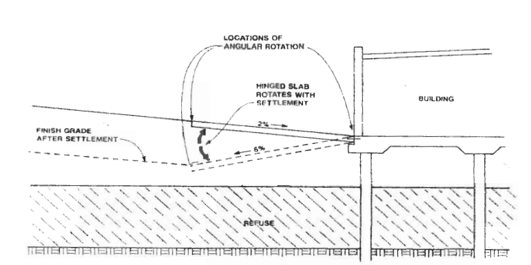
Figure 2: Flexible utility connection (Law, 2007)

Settlement of Waste Layers
For any landfill end-use, but especially for end-uses including construction of buildings, it is critical to estimate as accurately as possible the settlement in a waste layer. Settlement of waste layers occurs due to primary consolidation, secondary consolidation, biodegradation of waste, and residual settlement. Many researchers have developed models for this, but most models are based off, or are calibrated versions of, the 1973 Sowers method. Sowers method is based off consolidation theory and resembles the traditional e-log p method. In Sowers’ method, primary settlement in a waste layer is calculated from the equation 1.

In this expression, S is the primary settlement in the waste layer, H is the initial thickness of the layer, Cc is the primary compression index, e0 is the initial void ratio of the waste, P0 is the initial vertical stress at the middle of the layer, and ∆P is the increase in vertical stress at the middle of the layer. The total primary settlement would then be the summation of primary settlements of each layer of waste considered. According to Sharma and Reddy (2004), the primary settlement is expected to occur within one to four months of loading.
The secondary settlement of a waste layer due to the self-weight of the waste is given by equation 2.
![]()
In Eq. 2, ∆HSW is the secondary settlement due to the self-weight of waste, Cα(SW) is the coefficient of secondary compression due to self-weight, t1 is the length of time for primary consolidation to take place, and t2 is the amount of time passed since the placement of the waste. Secondary settlement due to external loads occurs at a different rate than that from self-weight, indicated in Equation 3, where Cα(EL)is the coefficient of secondary compression due to an external load.
![]()
Therefore, the total settlement is given by equation 4.
![]()
At long time periods, the secondary settlement of waste layers starts to become very large compared to soil materials. This model is not perfect because even if the designer calibrates the model to their site, it does not account for the waste degradation in the correct way. However, the model gives a good enough estimate that it continues to be used today.
Although Sowers’ method is the most well-known model for MSW settlement, other models have been proposed in attempts to more accurately reflect the degradation behavior of the waste. For example, Chen and Chen (2011) developed a numerical model to solve a differential equation that includes effects of pore gas diffusion gradients and biodegradation models. The model is calibrated to calculate the accumulation of gas in the waste layer with time along with the transportation of the gas out of the system that leads to settlement under the weight of the waste. This model has been validated against field data as shown in Figure 3.
Figure 3: Simulation results of the Mission Canyon landfill settlement (Chen and Chen, 2011).

There are several methods available to attempt to reduce secondary compression settlement. Sharma and Reddy suggest dynamic compaction, grouting, or surcharge loading. However, according to Coduto et al. (2016), dynamic compaction typically has an effective zone of about 15 to 30 feet. Therefore, for deep landfills, this method would not have the range to densify all of the waste material. Coduto also claims that due to the large impact forces of dynamic tamping, shock waves can be damaging to nearby existing structures. Therefore, great care should be taken to protect important landfill systems such as the gas and leachate collection systems, and geomembranes. Grouting could theoretically be a good way to fill voids left by decomposed waste and by adding stiffness to the material, thereby reducing secondary settlement. This would probably need to be done before placement of geomembranes to avoid penetration during the grouting process. Perhaps the easiest way to reduce secondary settlement would be by surcharge loading. According to Coduto, surcharge loading requires years in order to be effective, but in the case of a landfill, time may not be an issue. When filling the landfill, the owners will probably have a stockpile of soil for daily cover on site—that can be a cheap source of surcharge load that requires no expertise to implement. Additionally, development doesn’t always take place directly after closure of the landfill, so there may be some downtime during which surcharging is a simple and cheap option. If surcharging is implemented, the Sowers method could easily be modified to include a recompression term for the waste. Again, it is best to use site-specific data to determine the coefficients of compression.
Energy Production from Landfill Gas
Landfill gas (LFG) produced from the biodegradation of organic waste is a major consideration that all landfills must account for during operational years and for many years after closure. The time period of LFG production can be lengthened if biodegradation rates are low, as is often the case due to the moisture-limited environment of a landfill. Landfill gas can be produced for up to 50 years after landfill closure (USEPA, 2005), thus a long-term plan for gas collection and control must be generated and adhered to. Since LFG can contain mercury, VOCs, and other HAPs, there is a great risk to humans and wildlife if the gas is inhaled (USEPA, 2005). Another hazard is the possibility of explosion if LFG is allowed to build up without proper ventilation. Whether or not the landfill is slated for a post-closure development, LFG must be able to vacate the landfill.
Typically, LFG is composed of half methane and half carbon dioxide, with trace amounts of other gases present. This methane can be harnessed and burned to produce electricity. Landfills that do not capture LFG for use as a power source either burn LFG with a flare or emmit it into the atmosphere. Since the passing of RCRA, direct release to the environment is no longer a practical option for new landfills in the United States (Bogner, 1990).
While all landfills will produce some amount of LFG, it is important to determine the anticipated composition of the waste for the landfill to determine if enough methane will be produced to be a feasible energy source. Certain landfills will not degrade enough material to produce economical quantities of methane. For example, landfills that are used to dispose of any kind of ash (incinerator, coal plant, etc.) will not be ideal candidates for LFG utilization (Bogner, 1990). However, landfills that take in a large quantity of wastewater treatment sludge are great candidates for LFG utilization, as the wastewater introduces high amounts of moisture and nutrients. As always, regardless of whether LFG will be harnessed as an energy source, the gas must be controlled and handled as required by legislation.
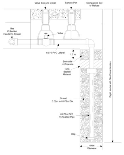
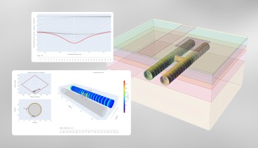
Landfill gas is generally collected and routed out of landfills through a passive or active system of wells and connector pipes. In a passive system, the wells are open to the atmosphere, and either escape directly (as in old/outdated systems) or are burned by flare before exiting. Passive systems are cheaper to operate and maintain, but in a large or topographically-challenging landfill, or in any system planning to use LFG as an energy source, an active system is necessary. Active systems operate the wells under vacuum or pressurized conditions to move LFG. These systems are always necessary when using LFG as an energy source, as the components work most efficiently when operated under steady state conditions (USEPA, 2005), which are easier to produce with the control offered by active systems. The design of the landfill collection system is dependent on each specific landfill site, with important factors being the composition of the waste and moisture conditions at specific locations (Xue et al, 2013). A typical gas collection well is shown in Figure 4.
Figure 4: Typical gas collection well (USEPA, 2005)
There are three typical methods of using landfill gas for energy production: direct use in a gas fired furnace or boiler for heat generation, on-site electricity generation via an internal combustion engine or turbine, and production of natural gas through removal of other trace gases and CO2 (Bogner, 1990). The third method is an emerging technology; the first two methods comprise almost all of the current LFG use (USEPA, 2017). Using LFG to generate heat or electricity both require combustion of the LFG gas and require a few special considerations. Untreated LFG can be used directly on site, but not transported as the amount of moisture in the gas is unfavorable (Ham, 1979). Thus, it is not uncommon to dehydrate the gas to acceptable moisture levels, as this also promotes complete combustion.
Traces of hydrogen sulfide and chlorinated hydrocarbons create an acidic environment that can corrode components, and siloxanes can lead to harmful deposits inside the turbine or engine (Storey et al, 2014). Scrubbers to remove hydrogen sulfide have been successful: a landfill in Albany, NY implemented a power-generation unit that passed a liquid reagent through the gas to remove H2S (Hansen and Bruce, 1997). If the hydrogen sulfide concentrations are not extreme, a robust, stainless steel engine or turbine might be sufficient to mitigate corrosion. However, almost any concentration of deposit-forming sulfur compounds and siloxanes will lead to a shortened lifespan of equipment, as these deposits build up and impair movement and proper combustion. For these reasons, it is typical for LFG to undergo further treatment to ensure longevity of the energy recovery system. Jet separation, a method that takes advantage of the difference in molecular weight of gases has been shown to be somewhat successful while proven methods of using carbon adsorption and refrigeration are still in use (Storey et al, 2014).
Renewable Energy Production- Solar and Wind
Solar
In certain areas of the United States where sunshine is abundant, transforming a closed landfill into a solar farm is an enticing possibility. Examples of these solar farms have been produced in the city of Houston and at the Sarasota County Landfill in Florida (Prajnasmita Mohapatra, et al, 2012).
Generally, there are two methods for converting solar energy to electricity. The method most commonly applied in the case of landfill end-uses is through the use of PV (photovoltaic) cells (Prajnasmita Mohapatra, et al, 2012). Within the realm of photovoltaic cells, there are two PV technologies that have been used extensively in commercial solar applications; crystalline silicon and thin film (USEPA, 2013). Silicon photovoltaic cells are the “traditional” solar panels; mounted on roofs or foundations that can either rotate or stay fixed. Thin film PV cells are either made from silicon or other non-silicate materials (cadmium), but like the name implies, are very thin; only a few micrometers thick. While crystalline silicon PV technology has a higher efficiency than thin film technology, thin film PV cells are so thin and flexible that they can be integrated into a landfill cover membrane (USEPA, 2013). In either case, these panels are placed where they can receive sunlight, and then directly convert the sunlight into electricity. When sunlight strikes a PV cell, the electrons within the layers of the PV cells begin to move from one layer to another, inducing an electric current (USEPA, 2013). This current can then either be stored (in batteries or the grid), or used directly to power appliances. The other method involves using a system of mirrors to heat liquid (water) to drive a turbine (Prajnasmita Mohapatra, et al, 2012). A clever PV application at a landfill near San Antonio, Texas, incorporated thin film photovoltaic cells into the final membrane cover, decreasing the amount of construction necessary for the landfill to produce electricity.
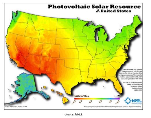
Closed landfills are seemingly great locations to harvest solar energy because they have large amounts of open space with no tree cover, roads, access, and runoff plans already available. However, the landfill site location must be evaluated to determine whether it receives enough sunshine to be economically viable. This is a function of the latitude, the region’s climate and (large-scale) topography, and the albedo of the earth (USEPA, 2013). Figure 5 shows a large-scale recommendation of the solar potential in the United States produced by NREL for use in an initial feasibility study and presented in USEPA, 2014.
Figure 5: Solar Energy Potential Map of United States
Additionally, consideration must be made to whether the cover system can handle the PV system foundations, as well as the construction loads experienced during placement of solar cells (Prajnasmita Mohapatra, et al, 2012). This consideration should ideally be considered in the initial design of the landfill, as solar panels are subjected to significant wind and snow loads in addition to gravity loads, depending on the climate and location. If the cover is able to withstand these loads, then the next consideration is topography. Landfills generally don’t have tremendously steep slopes, but solar panels perform best when oriented at the angle of incidence, the angle at which the panels are perpendicular to the ray of incoming sunlight (Prajnasmita Mohapatra, et al, 2012). The maximum potential is when the panels are perpendicular to the ray of the incoming sunlight. Thus, if the panels are on movable mounts, it is ideal to have them track the sun exactly. If the slope and foundation cannot support the solar panel at this angle, then the slope should be modified, or a different location should be chosen for the solar panels. This issue was mitigated at the San Antonio landfill by integrating the PV cells directly into the cover membrane. In this way, slope stability was not an issue.
Wind Energy
Similarly to solar power, wind energy can also be harnessed as a renewable energy source at a closed landfill site, but there are less documented cases of wind energy generation at these sites (USEPA, 2014). The economical advantage of producing wind power at a closed landfill site is heavily dependent on the amount of wind present at the site. NREL has also developed a wind resource map for use in a preliminary feasibility study, presented in Figure 6. Areas of concern when designing for wind energy production are settlement, bearing capacity, and liner integrity. Bearing capacity requires special consideration because of the large axial and lateral forces experienced by wind turbines, and the liner must be designed in a way that the turbine foundations do not compromise the liner.
Figure 6: Wind Energy Potential Map of United States

Other Uses for Closed Landfills
Agriculture
It is possible to use a closed landfill for agricultural use and appears to be an attractive option due to the large open area atop a landfill (USEPA, 2014). A major advantage of using a closed landfill for agricultural development is that structures causing excessive settlement and requiring foundations are not necessary. However, that does not mean that no special planning is involved. The grading and irrigation plan for the agricultural space must be compatible with the typical regulations regarding runoff and management of waste. If agriculture is the intended end use, it would be wise to integrate the designs, saving money from redesigning and grading later. Special concerns related to agricultural use are contamination of crops from landfill emissions, and protecting the cap from damage from agricultural activities. As with recreational end uses, this could mean adding thicker layers of topsoil to avoid root penetration and damage from machines. Although a properly managed landfill closure would ensure the integrity of the liner and avoid contamination anyway, several states have banned the use of the land for agriculture, while other states evaluate permittance of agricultural use on a case-by-case basis. Therefore, the landfill owner should consult state and local laws to determine if agriculture is a viable option.
Landfill Mining
Landfill mining has a wide variety in application and purpose. Burlakovs et al. (2017) discusses the state of landfill mining globally and discusses various reasons why landfill mining is applied. Figure 7 shows the distribution of types of landfill mining projects in Europe, USA, and Asia. Notably, resource reclamation is not typically the primary purpose for landfill mining except in Asia, being less popular than pollution reduction, recultivation of the site, and voidspace recovery in Europe and USA. Landfill mining can be a useful tool in reclaiming land to be used for other end uses described in this paper, but landfill mining itself is not the end use of the landfill. However, as is always the case, planning ahead for landfill mining will save money on redesigning and extra work down the road. Landfill owners can methodically group together waste materials that are expected to be worth reclaiming at a future time, reducing the cost of excavating and separating out the useful materials and increasing the quality of reclaimed materials. Overall, according to Krook (2012), landfill mining is a somewhat immature field that requires more research and experience to develop standard practices for operation. He also claims that much of the known information about landfill mining is owned by contractors experienced in landfill mining and is not based on research. Thus, more research should augment our current experience to further develop the field of landfill mining.
Figure 7: Purpose for landfill mining projects in Europe, North America, and Asia (Kurlakovs et al., 2017)

Conclusion
Many possibilities exist for post-closure landfill development. The large, open tract of land is amenable to many end-uses, the most popular of which include recreation, solar farms, and landfill gas usage. Less commonly, but which increasing frequency are structural/commercial developments. It is beneficial to the landowner to plan as far ahead of time as possible for the intended end use, if possible, to save time and money on design and development. Many factors discussed in this paper will help determine the appropriateness of alternatives for landfill end-use. However, all landfill site are unique in some way and will require judgement by engineers, governing bodies, and the public. As more landfills close, we will continue to see new and creative solutions to engineering problems on these sites.
References
- Best practices for siting solar photovoltaics on municipal solid waste landfills. (2013). S.I.: United States Environmental Protection Agency.
- Bogner, J.E. (1990). Energy potential of modern landfills. United States. Retrieved from http://www.osti.gov/scitech/servlets/purl/6272010
- Burlakovs, J., Kriipsalu, M., Klavins, M., Bhatnagar, A., Vincevica-Gaile, Z., Stenis, J., . . . Hogland, W. (2017). Paradigms on landfill mining: From dump site scavenging to ecosystem services revitalization. Resources, Conservation and Recycling,123, 73-84. doi:10.1016/j.resconrec.2016.07.007
- Chen, Kuo-Sheng, Rong-Her Chen, and Chia-Nan Liu. "Modeling municipal solid waste landfill settlement." Environmental Earth Sciences 66, no. 8 (2011): 2301-309. doi:10.1007/s12665-011-1453-6.
- Coduto, D. P., Kitch, W. A., & Yeung, M. R. (2016). Foundation design: principles and practices. Boston: Pearson.
- Evaluating, optimizing, or ending post-closure care at municipal solid waste landfills based on site-specific data evaluations. (2006). Washington, DC: Interstate Technology and Regulatory Council, Alternative Landfill Technologies Team.
- Hansen, David and Bruce, Willard (1997). Albany Interim Landfill gas extraction and mobile power system: Using landfill gas to produce electricity. Final report. United States. doi:10.2172/495761
- Krook, J., Svensson, N., & Eklund, M. (2012). Landfill mining: A critical review of two decades of research. Waste Management,32(3), 513-520. doi:10.1016/j.wasman.2011.10.015
- Law, J., P.E. (n.d.). Post-closure landfill closure end uses and development: technical issues and cases studies. 2007. Retrieved January 16, 2017, from http://www.scsengineers.com/scs-white-papers/closed-landfill-post-closure-end-uses-and-development-technical-issues-and-case-studies-james-law-presented-in-beijing-china/
- Mackey, R. E. (1996). Three end-uses for closed landfills and their impact on the geosynthetic design. Geotextiles and Geomembranes,14(7-8), 409-424. doi:10.1016/0266-1144(96)00025-8
- Mohapatra, P., Ali, S. M., Mishra, S. P., & Pradhan, A. (2012). Future Apects Solar Panel Installation On Closed Landfills. International Journal of Advances in Engineering & Technology, 4(2), 324-332.
- Robertson, T., & Dunbar, J. (2005). Guidance for evaluating landfill gas emissions from closed or abandoned facilities. Washington, DC: U.S. Environmental Protection Agency, Office of Research and Development.
- Sharma, H. D. and Reddy, Krishna R. (2004). Geoenvironmental engineering: site remediation, waste containment, and emerging waste management technologies. Hoboken, N.J: Wiley.
- Sowers, G.F., Settlement of Waste Disposal Fills, in Procedings of the 8th International Conference on Soil Mechanics and Foundation Engineering, Moscow, 1973.
- Storey, John Morse, Theiss, Timothy J, Kass, Michael D, FINNEY, Charles E A, Lewis, Samuel, Kaul, Brian C, … Sepaniak, Michael. (2014). Fuel Flexibility: Landfill Gas Contaminant Mitigation for Power Generation. United States. doi:10.2172/1130430
- USEPA. Closed Waste Sites as Community Assets: A Guide for Municipalities, Landfill Owners, and Regulators. (2014). Retrieved from https://nepis.epa.gov/
- Wagner, T. P., & Raymond, T. (2015). Landfill mining: Case study of a successful metals recovery project. Waste Management,45, 448-457. doi:10.1016/j.wasman.2015.06.034
- Ham, R. K. (1979). Recovery, processing, and utilization of gas from sanitary landfills. Cincinnati, Ohio: Environmental Protection Agency, Office of Research and Development, Municipal Environmental Research Laboratory.
 Ryan Carpus
  Phil Koerschner
 Industry News


Events

19th European Conference on Soil Mechanics and Geotechnical Engineering, Istanbul, Türkiye
The 10th International Congress on Environmental Geotechnics

11th European Conference on Numerical Methods in Geotechnical Engineering

1st International Conference on Sustainability in Geotechnical Engineering (ICSGE 2027)

The 4th International Conference on Press-in Engineering 2027 (ICPE2027)

International Symposium on Cone Penetration Testing (CPT'27)

Rocscience International Conference 2027: Geotechnics, Structures & Hydro in the Age of AI
IS-GI Lyon 2027: International Symposium on Ground Improvement


4 COMMENTS
Eva*
Dec, 05, 2017 Very interesting and well-structured report, with lots of info! Just a remark: I found the 'Recreational uses' text a bit long and difficult to read. I think putting subcategories at this section would help (ex. 'Concerns regarding such uses', or some relevant pictures. Ryan Carpus
Dec, 14, 2017 Eva,Thanks for the input on the recreation uses section. Subcategories make this section much easier to read or skim over, and the section looks better now.
Edit Comment
Ronald*
Dec, 14, 2017 Dear Ryan and Phil,thanks for the review. Did you find any case histories that include containment layers with geosynthetics that were penetrated by deep foundations?
Ryan Carpus
Dec, 19, 2017We didn't come across any cases where a geosynthetic membrane was penetrated, although that doesn't mean there isn't anything that we missed, especially since many case studies only comment on the aspects of design that the author cares about. We have, however, come across cases where the developers went out of their way to prevent geosynthetic penetration from happening. For example, the Sanlando Landfill facility in Seminole County, Florida, was planned to be converted to a softball complex that had many deep poles in the design. In this case, they were able to meet the minimum cap requirements by just using a CCL for most of the cap, and using geomembrane under shallow building foundations as part of the LFG control (Mackey, 1997).
Edit Comment